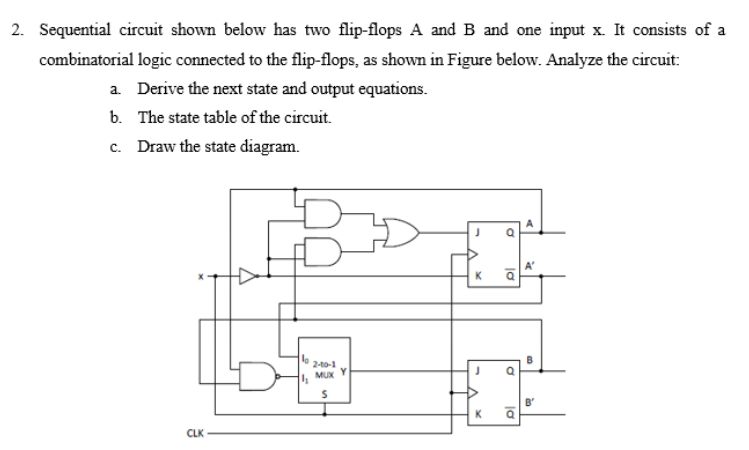
2. Sequential circuit shown below has two flip-flops A and B and one input x. It consists of a combinatorial logic connected to the flip-flops, as shown in Figure below. Analyze the circuit: a. Derive the next state and output equations. b. The state table of the circuit. c. Draw the state diagram. A 2-10-1 MUX B' CLK
Q: Flip flop input and output equations for a sequential circuit with 3 flip flops (A, B and C), 2…
A: State Diagram is:
Q: A sequential circuit using a D flip-flop and logic gates is shown in the figure, where X and Y are…
A: J-K Flip-flop- The J-K flip flop is the same as the S-R flip-flop with the addition of a clock input…
Q: On a digital circuit with three switch inputs, LED operates when two or three of the switches are 1’…
A: Explanation: a. There are three switches let the switches are A, B, and C. And let the LED is…
Q: Flip flop input and output equations for a sequential circuit with 2 flip flops (A and B), 1 input…
A: given A(t+1) = A’X + BX' B(t+1) = AX’ + B'X Z = A’B'X'
Q: For the input waveforms in Figure, what logic circuit will generate the output waveform shown?…
A: Given : Here in the given question they have mentioned the input and output waveforms of a digital…
Q: 4- A sequential circuit with two D flip-flops A and B, two inputs, x and y; and one output z is…
A:
Q: Sequential circuit shown below has two flip-flops A and B and one input x. It consists of a…
A:
Q: For a sequential circuit with 3 flip flops A, B and C and 1 X input input equations are as follows.…
A: Step 1: Draw state table State table : Present state Input Next state A B C X A' B' C' 0 0 0…
Q: 6. In your notebook, sketch a 2-bit asynchronous counter using D flip-flops and a HEX display,…
A: Note: Since you have posted multiple independent questions in the same request, we will solve the…
Q: Design a synchronous counter that will count according to the following sequence: D-1-6 -7-3 and…
A: We need to design synchronous counter by using of T flip flops . First we will draw truth table for…
Q: A Mealy sequential circuit has one input, one output, and two flip-flops. The timing diagram for…
A:
Q: :D nalyze the following sequential circuit: O What type of state machine is this circuit and why?…
A: We need find out input and output expression for given state machin circuit .
Q: 12) Study the ladder logic program in the figure below and answer the questions that follow: a. What…
A:
Q: Analyse the sequential circuit shown in Figure 1 which has 2 rising edge-triggered flip-flops A and…
A: PART (A) Flip Flop equations: DA = X'+XA = X'+A JB = X'A+X'B JB = X'(A+B) KB = XB' State equation:…
Q: A sequential circuit has one input, X. When X = 0, the states of the circuit remain the same. When X…
A:
Q: Consider the multiplexer based logic circuit shown in the figure w MUX MUX ·F 1 Select one: O a. W…
A: Given diagram,
Q: 9) In a ladder logic program, one should never A) use the name of a coil for a contact B) use the…
A:
Q: what are the application of Flip – Flop. b- What is the difference between the Flip – Flop circuit…
A: In this question we will write about applications of flip flops...
Q: Inputs B Output X For the input waveforms, draw the combinational logic circuit that will generate…
A: Digital electronics problem.
Q: On a digital circuit with three switch inputs, LED operates when two or three of the switches are l'…
A:
Q: A counter circuit is shown in Figure Q4(b). Redesign this counter using two T flip-flops and logic…
A:
Q: Name the logic circuit AD inputs output B. Find the expression of F and simplify
A:
Q: What type of state machine is this circuit and why? 2) Write equations for flip-flop inputs and…
A:
Q: You want to design a synchronous counter sequential logic circuit. Counting from 0 to 9 will perform…
A: Following are the steps involved for designing counter Design the numbers flip flop Write…
Q: You want to design an arithmetic adder / subtractor logic circuit. a) List the steps you will apply…
A: to design an arithmetic adder / subtractor logic circuit.
Q: 2. Sequential circuit shown below has two flip-flops A and B and one input x. It consists of a…
A:
Q: Draw the logic diagram
A:
Q: Flip flop input and output equations for a sequential circuit with 3 flip flops (A, B and C), 2…
A:
Q: Design a 29 to 00 down counter using JK flip-flops. The circuit should be simulated using bcd 7…
A:
Q: A sequential circuit with two D flip-flops, A and B; two inputs, x and y; and one output, z, is…
A:
Q: answere fast please question from DIGITAL LOGIC DESIGN TOPIC : Designing Combinational Logic You…
A: In the design, there is the representation of the water level circuit which indicates the water…
Q: What type of state machine is this circuit and why? 2) Write equations for flip-flop inputs and…
A: We need to tell about type of machine and we need to find input and output for flip flop .
Q: 2. A sequential circuit with two D flip-flops A and B, two inputs X and Y, and one output Z is…
A:
Q: The process steps required for synchronous counter design are written below. In which option is it…
A: To design a synchronous counter the following steps to be followed:
Q: JA = Bx + B'y' JB = A'x z = Ax'y' + Bx'y' KA = B'xy' KB = A + xy'
A: a) Logic diagram
Q: Design a combinational circuit that has 4-input (A.B.C.D) and one output (F) the output will be high…
A: STANDARD SUM OF PRODUCT FORM: In standard SOP form, the function is the sum of a number of product…
Q: Design a counter that counts 1-2-3-5-7 Please explain the following:state diagram state table…
A:
Q: The flip-flops in the drawing below are positive edge triggered D flip-flops. Let Q2, Q1, QO = 0,0,0…
A: D Flip-flop acts as a data transfer element. When an appropriate clock is provided, data at the…
Q: Design a logic circuit that controls the passage of a signal A according to the following…
A: In this question we design a logic circuit that controls the passage of a signal A according to the…
Q: Design a combinational logic circuit that will function as a building alarm device. Monitored are…
A:
Q: The state diagram is a basic 3-bit Gray code counter. This particular circuit has no inputs other…
A:
Q: The sequential circuits consist of a combinational circuit and storage elements. b The storage…
A: yes it is TRUE a) The sequential circuits consist of a a combinational circuit and storage…
Q: 12) Study the ladder logic program in the figure below and answer the questions that follow: a. What…
A:
Q: QUESTION 4 a) A sequential circuit has two D flip flops A and B with one input X and one output Y.…
A: Given:
Q: A sequential circuit with two D flip-flops A and B, two inputs, x and y; and one output z is…
A:
Q: Problem 4: Design a sequential circuit with the finite state machine shown in Table 2, using D…
A:
Q: A sequential circuit with two D flip-flops D1 and D2, two inputs x and y, and one output z is…
A: PART (A): LOGICAL DIAGRAM
Q: 6 For the state machine shown in Figure Q6 do the following: (a) Is this a Moore Machine or a Mealy…
A: As per our guidelines we are supposed to be answer the first three subparts only. Kindly repost the…
Q: note: just give me a idea to solve this question if you find it complex question from DIGITAL LOGIC…
A:
Q: Analyze the following sequential circuit: 1) What type of state machine is this circuit and why? 2)…
A: The solution is shown in the next step
Step by step
Solved in 2 steps with 2 images
- (a) Construct the state table and determine the state equation of this circuit. (b) Consider the following three different approaches of implementing the sequential logic circuit Sketch the logic diagram of the circuit for each case (i) Use a negative-edge triggered D flip-flop and some primitive gates (i) Use a positive-edge triggered JK flip-flop and some primitive gates (ii) Use a positive-edge triggered T flip-flop and a 4x1 multiplexerA sequential circuit has two JK flip-flops A and B, two inputs x and y, and one output z. The flip-flop input equations and circuit output equation are attached below: a) Draw the logic diagram of the circuit. b) Derive the state equations for A and B c) Tabulate the state table. d) Draw the state diagram for the circuit and describe the function of circuit.a) Design a logic circuit with three inputs A, B, C and an output that goes LOW only when A is HIGH while B and C are different. Draw and upload the circuit if you can, or at least describe it in words. b) Which logic gates produce a 1 output in the disabled state? c) Which logic gates pass the inverse of the input signal when these gates are enabled? d) What is the normal resting state of the SET’ and RESET’ inputs of a latch circuit (the prime is same as bar)? What is the active state of each input? e) What is the normal resting state of the NOR latch inputs? What is the active state?
- 3- Design a counter with a control input. When the input is high, the counter should sequence through three states: 10, 01, 11 and repeat. When the input is low the counter should sequence through the same states in the opposite order 11, 01, 10 and repeat.a) Draw the state diagram and state transition table.b) Implement the counter using D flip-flops and gates.A coin-operated cold drink dispenser will provide cold drink (D) under the following conditions: The correct coin (C) is inserted AND A paper cup is in position (P) AND The selector is set t Orange (O) OR Sprite (S) OR Lemonade (L) Write the Boolean expression for the output of the dispenser. Represent the operation of the dispenser in logic circuit 4 get a logic circuit to mimic corporate checking system for operators of a companyB) A coin-operated cold drink dispenser will provide cold drink (D) under the following conditions: The correct coin (C) is inserted AND A paper cup is in position (P) AND The selector is set t Orange (O) OR Sprite (S) OR Lemonade (L) Write the Boolean expression for the output of the dispenser. Represent the operation of the dispenser in logic circuit 4 get a logic circuit to mimic aorporate checquing system for operatore of a compnny
- 1. Asequential circuit with two D flip-flops A and B, two inputs, x and y ; and one output zis specified by the following next-state and output equationsA(t + 1) = xy’+ A’y‘B(t + 1) = xB+ B‘+ xB’z = A‘B(a) Draw the logic diagram of the circuit.(b) Draw the corresponding state diagram. 2.A sequential circuit has two JK flip-flops A and B and one input x . The circuit is describedby the following flip-flop input equations:JA = A‘x’+ B’KA = A’+ By’JB = A’+ xB’KB = AB+ xy’z = B‘y‘ + Bx‘y’(a) Draw the logic diagram(b) Draw the state diagram of the circuit.Create a synchronous counter utilising J-K flip-flops that may be utilised for a 7-story building's elevator system, as depicted in figure below. Assume the ground floor is considered the 0th floor. Assume that level 2 and level 7 cannot be reached because they are only accessible to authorised individuals. Provide the smallest number of logic gates in the logic circuit design.You are tasked to design a control unit for a light display. The light display design has three light components, see Figure 4.1a. Design a state machine that will control the sequence of the display (see Figure 4.1b). Your design should include three edge triggered D flip-flops, with each of the components controlled by one D flip-flop. Individual states of the sequence have been pre-defined (see Figure 4.1b), and the sequence should be run as an infinite loop. Any unused states can be treated as Don’t Cares. Your answer should include the following: a) A state diagram for the monitoring unit. b) A transition table. c) Based on the transition table in part b), use Karnaugh Maps to derive input equations the three D flip-flops. Show the full circuit design for the display control unit. Use a block diagram for each D flip-flop.
- Solve the following in Boolean Algebra: (BC'+A'D)(AB'+CD') A. Simplify the given function using Boolean simplification. B. Draw the logic diagram of the given equation. C. Draw the logic diagram of the simplified equation. D. Give the number of of logic gates used in the given design E. Give the number of logic gates used in the simplified design.A coin-operated cold drink dispenser will provide cold drink (D) under the following conditions: The correct coin (C) is inserted AND A paper cup is in position (P) AND The selector is set t Orange (O) OR Sprite (S) OR Lemonade (L) Write the Boolean expression for the output of the dispenser. Represent the operation of the dispenser in logic circuit 4 get a logic circuit to mimic aorporate checquing system for operatore of a compnnyCreate a logic diagram out of this boolean expression. CD+BD+BC+AD+AC+AB Note: All inputs A B C and D must be together.