2. What design parameters of the half wave single-phase rectifier?

Electricity for Refrigeration, Heating, and Air Conditioning (MindTap Course List)
10th Edition
ISBN:9781337399128
Author:Russell E. Smith
Publisher:Russell E. Smith
Chapter12: Electronic Control Devices
Section: Chapter Questions
Problem 4RQ: What is the difference between a diode and rectifier?

Related questions
Question
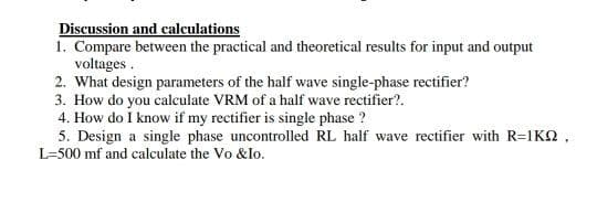
Transcribed Image Text:Discussion and calculations
1. Compare between the practical and theoretical results for input and output
voltages .
2. What design parameters of the half wave single-phase rectifier?
3. How do you calculate VRM of a half wave rectifier?.
4. How do I know if my rectifier is single phase ?
5. Design a single phase uncontrolled RL half wave rectifier with R=1KQ ,
L=500 mf and calculate the Vo &lo.
Expert Solution
This question has been solved!
Explore an expertly crafted, step-by-step solution for a thorough understanding of key concepts.

Step by step
Solved in 2 steps with 1 images

Knowledge Booster


Learn more about
Need a deep-dive on the concept behind this application? Look no further. Learn more about this topic, electrical-engineering and related others by exploring similar questions and additional content below.Recommended textbooks for you
Electricity for Refrigeration, Heating, and Air C…
Mechanical Engineering
ISBN:
9781337399128
Author:
Russell E. Smith
Publisher:
Cengage Learning

Electricity for Refrigeration, Heating, and Air C…
Mechanical Engineering
ISBN:
9781337399128
Author:
Russell E. Smith
Publisher:
Cengage Learning