
Structural Analysis
6th Edition
ISBN: 9781337630931
Author: KASSIMALI, Aslam.
Publisher: Cengage,
expand_more
expand_more
format_list_bulleted
Related questions
Question
For the beam in the question above, determine the maximum shear stress. sketch the
section stress distribution.
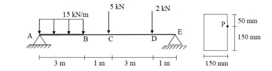

Transcribed Image Text:5 kN
2 kN
15 kN/m
50 mm
E
150 mm
3 m
1 m
3 m
1 m
150 mm
Expert Solution
This question has been solved!
Explore an expertly crafted, step-by-step solution for a thorough understanding of key concepts.

Step by stepSolved in 4 steps with 3 images

Knowledge Booster

Similar questions
- The rectangular plate is deformed into the shape shown by the dashed lines. Suppose that a = 260 mm and b = 450 mm (Figure 1) 2 mm a mm D B 6 mm 6 mm 2 mm -3 mm -x 1.) Determine the average normal strain along diagonal BD. 2.) Determine the average shear strain Yzy at corner B relative to the x, y axes..arrow_forwardConsider a point in a structural member that is subjected to plane stress. Normal and shear stress magnitudes acting on horizontal and vertical planes at the point are Sx = 72 MPa, Sy = 12 MPa, and Sxy = 39 MPa. (a) Draw Mohr's circle for this state of stress. (b) Determine the principal stresses and the maximum in-plane shear stress acting at the point. (c) Show these stresses on an appropriate sketch (e.g., see Fig. 12.15 or Fig. 12.16). (d) Determine the absolute maximum shear stress at the point. Sxy S Answer: (a) Draw Mohr's Circle for this state of stress. (b) Op1 = i MPa Op2 = i MPa Tmax in-plane i MPa (c) Show these stresses on an appropriate sketch (e.g., see Fig. 12.15 or Fig. 12.16) (d) Tabs max i MPaarrow_forwardProblem 5: The stresses on the x-y-axes are o, = 8 ksi, o, = 12 ksi, and Ty = -5 ksi. Draw the Mohr's circle for this stress state. Identify the maximum shear stress from the Mohr's circle, and draw the maximum shear stress element, specifying its orientation.arrow_forward
- Consider a point in a structural member that is subjected to plane stress. Normal and shear stress magnitudes acting on horizontal and vertical planes at the point are S, = 8.0 ksi, S, = 10.5 ksi, and Sxy = 8.0 ksi. (a) Determine the principal stresses and the maximum in-plane shear stress acting at the point. (b) Show these stresses on an appropriate sketch (e.g., see Figure 12.15 or Figure 12.16) (c) Compute the absolute shear stress at the point. Sy Sxy S.arrow_forwardThe triangular plate is fixed at its base, and its apex A is given a horizontal displacement of 5 mm. Calculate the shear strain, Yxy, at A. Also, calculate the average normal strain & along the x' axis. 800 mm 45% 45° 800 mm 5 mmarrow_forwardPlease help me with this question.arrow_forward
arrow_back_ios
arrow_forward_ios
Recommended textbooks for you
 Structural Analysis (10th Edition)Civil EngineeringISBN:9780134610672Author:Russell C. HibbelerPublisher:PEARSON
 Principles of Foundation Engineering (MindTap Cou...Civil EngineeringISBN:9781337705028Author:Braja M. Das, Nagaratnam SivakuganPublisher:Cengage Learning
 Fundamentals of Structural AnalysisCivil EngineeringISBN:9780073398006Author:Kenneth M. Leet Emeritus, Chia-Ming Uang, Joel LanningPublisher:McGraw-Hill Education
 Traffic and Highway EngineeringCivil EngineeringISBN:9781305156241Author:Garber, Nicholas J.Publisher:Cengage Learning
Structural Analysis (10th Edition)
Civil Engineering
ISBN:9780134610672
Author:Russell C. Hibbeler
Publisher:PEARSON
Principles of Foundation Engineering (MindTap Cou...
Civil Engineering
ISBN:9781337705028
Author:Braja M. Das, Nagaratnam Sivakugan
Publisher:Cengage Learning
Fundamentals of Structural Analysis
Civil Engineering
ISBN:9780073398006
Author:Kenneth M. Leet Emeritus, Chia-Ming Uang, Joel Lanning
Publisher:McGraw-Hill Education
Traffic and Highway Engineering
Civil Engineering
ISBN:9781305156241
Author:Garber, Nicholas J.
Publisher:Cengage Learning