
Introductory Circuit Analysis (13th Edition)
13th Edition
ISBN: 9780133923605
Author: Robert L. Boylestad
Publisher: PEARSON
expand_more
expand_more
format_list_bulleted
Related questions
Concept explainers
Question
The question is in photo
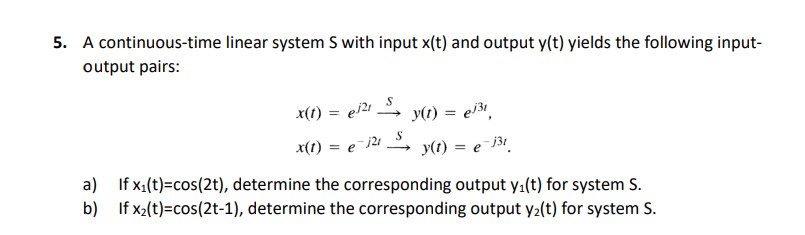

Transcribed Image Text:5. A continuous-time linear system S with input x(t) and output y(t) yields the following input-
output pairs:
x(1) = ei2i
y(1) = el3,
x(1) = e-j21
y(1) = e-13!.
a)
If x.(t)=cos(2t), determine the corresponding output y1(t) for system S.
b) If x2(t)=cos(2t-1), determine the corresponding output y2(t) for system S.
Expert Solution
This question has been solved!
Explore an expertly crafted, step-by-step solution for a thorough understanding of key concepts.

This is a popular solution

Trending nowThis is a popular solution!

Step by stepSolved in 2 steps with 2 images

Knowledge Booster


Learn more about
Need a deep-dive on the concept behind this application? Look no further. Learn more about this topic, electrical-engineering and related others by exploring similar questions and additional content below.Similar questions
- Using the definition of power-type and energy-type signals, 1. Show that x(t) = Aei(2n fot +®) is a power-type signal and its power content is A?. A? 2. Show that x(t) = A cos(2t fot + 0) is powertype and its power i - 3. Show that the unit-step signal u-1(t) is a power-type signal and find its power content. 4. Show that the signal Kr- t>0 x(t) : t<0 is neither an energy-type nor a power-type signal.arrow_forwardQUESTION 4 Consider a linear circuit having input voltage Vin (t) and a corresponding output voltage Vout (t). Which of the following statements concerning time varying input and output is certainly true: a) When the input is exponential Vin(t) = e³₁t with some value $₁, the output must also be exponential Vout(t) = Aes2t with S₂ and s₁ being different in general. b) When the input is exponential Vin(t) = es₁t with exponential constant S₁, the output must also be exponential Vout (t) = = AeS₁t only if s₁is a real number, while A could be either real or complex number. c) When the input is exponential Vin(t) = es₁t with some exponential constant S₁, the output must also be exponential Vout (t) = AeS₁t, where both s₁ and A can be real or complex numbers d) None of the above a)arrow_forwardSome practice questions for class test(1).pdf - Adobe Acrobat Reader DC (32-bit) File Edit View Sign Window Help Home Tools Some practice ques... x UNIVERSITY OF UL.. 早2 画Q 21 180% Search 'Crop P (b) For the comparator circuit shown below, a sinusoidal input signal with a peak voltage P Export F Edit PD (Vp) of 5 V and a frequency of 1 Hz is applied to the non-inverting terminal. Assume +Vcc Create as +12V and -Vcc as -12 V, with corresponding saturation voltages of +Vsat of +11 V and - Comm Vsat of -11 V and R1 and R2 values of 100 kM and 50 kN, respectively. Assuming that the i Comb El Orgar signal frequency is well below the slew rate limit, describe and draw what would be the Delete, insert rotate pages. comparator output. Cor +Vcc A Rec Vin Pro 5 V VN Ac +Vcc V Vo to R1 R2 1 s -Vcc DELL く P. 近arrow_forward
- (a) A discrete-time signal x[n] is shown in Figure 1. x[n] 3 1 -1 Figure 1: Discrete-time Signal x[n] (i) Sketch and label x[2n] - x[n- 1] (ii) Sketch and label 2x[n]{u[n] - u[-n] }arrow_forward101] The discrete-time signals in Figure below are plotted as shown to plot the following: i-xa[2n], ii-xa[-n/4], iii- Xb[-5 - n] find z(n)= x₁[-n+1] + x[n+1], and plot the signal z(n). plot 2xb[n]+2. . . find an even and odd parts of the signal in Xa(n). determine the energy for the signals xb(n) [u(n-1)-u(n-5)] and S = 5 -6-5- 11171 2 3 4 -3-2--1₁ -2 n=al 0 (a) 567 *** T!!! 11 -3 (24 (9 -6-5-4-3 xa(n)[u(-n+3)-u(n-4)] 012345 11 Luffiarrow_forwardGiven the two signals below, find a) the autocorrelation of x[n] b.) the autocorrelation of z[n] c.) the convolution of x[n] & z[n] using any method and lastly d) the cross correlation of these two signals. Show your solution.arrow_forward
- 7- The unit-step response of a linear control system is shown in Figure QIB. Find the transfer function its corresponding second-order prototype system. Figure Q1B 0.4 0.35 0.3 0.25 0.2 0.15 0.1 0.05 0.5 1 1.5 2 2.5 3 3.5 4.5 5 Time əsuodsəyarrow_forwardThis figure shows the block diagram representation of a compensator U(s)/E(s). E(S) U(s) K Ko TIS 1 + 7₁s 1+T₂s Prove that this block diagram can be reduced into a PID controller with the three gains for the proportional, derivative, and integrator components. Derive these con- stants, i.e., derive Kp. Ti, Ta in terms of Ko, T₁, T2, K, by obtaining the CLTF for the above system. Your answer should look like: GPID (5) = Kp (1 +7 +Tas).arrow_forwardProblem1) The following set of four waveforms is to be used for transmission across the standard AWGN channel. Assume that b = 6/T s1(t) s2(t) s3(t) s4(t) t T t T -b -b (a) Give an orthonormal basis for these waveforms. (b) Sketch the signal space characterization of this set of waveforms, i.e., the signal points s1, $2; S3; S4. (c) Determine the energy of each of the waveforms.arrow_forward
- Ineed answer within 20 minutes please please with my best wishesarrow_forwardA Some practice questions for class test(1).pdf - Adobe Acrobat Reader DC (32-bit) File Edit View Sign Window Help Home Tools Some practice ques... X UNIVERSITY OF UL.. Sign In 2/3 180% Q.4 Search Crop Page (a) For the comparator circuit shown below, a a sinusoidal input signal with a peak 2 Export PDF voltage (Vp) of 5 V and a frequency of 1 Hz is applied to the non-inverting terminal. DE Edit PDF Assuming that the signal frequency is well below the slew rate limit, describe and draw Create PDF E Comment what would be the comparator output. i Combine Files Assume values of +Vcc as +12V and -Vcc as -12 V, with the corresponding output I Organize Pages saturation voltages of +Vsat of +11 V and -Vsat of -11 V. Delete, insert extract and rotate pages Try now A Compress PDF +Vcc 2 Redact Vin 5 V VN Protect Adobe Sign Fill & Sign Vref Vo Send for Co -Vcc More Tools 1 s ^ D ENG 15 DELL ntel 近arrow_forwardplease provide sketch!!!!! Please answer in typing format please ASAP for the like pleasearrow_forward
arrow_back_ios
SEE MORE QUESTIONS
arrow_forward_ios
Recommended textbooks for you
- Introductory Circuit Analysis (13th Edition)Electrical EngineeringISBN:9780133923605Author:Robert L. BoylestadPublisher:PEARSON
 Delmar's Standard Textbook Of ElectricityElectrical EngineeringISBN:9781337900348Author:Stephen L. HermanPublisher:Cengage Learning
 Programmable Logic ControllersElectrical EngineeringISBN:9780073373843Author:Frank D. PetruzellaPublisher:McGraw-Hill Education
  Fundamentals of Electric CircuitsElectrical EngineeringISBN:9780078028229Author:Charles K Alexander, Matthew SadikuPublisher:McGraw-Hill Education
 Electric Circuits. (11th Edition)Electrical EngineeringISBN:9780134746968Author:James W. Nilsson, Susan RiedelPublisher:PEARSON
 Engineering ElectromagneticsElectrical EngineeringISBN:9780078028151Author:Hayt, William H. (william Hart), Jr, BUCK, John A.Publisher:Mcgraw-hill Education,
Introductory Circuit Analysis (13th Edition)
Electrical Engineering
ISBN:9780133923605
Author:Robert L. Boylestad
Publisher:PEARSON
Delmar's Standard Textbook Of Electricity
Electrical Engineering
ISBN:9781337900348
Author:Stephen L. Herman
Publisher:Cengage Learning
Programmable Logic Controllers
Electrical Engineering
ISBN:9780073373843
Author:Frank D. Petruzella
Publisher:McGraw-Hill Education
Fundamentals of Electric Circuits
Electrical Engineering
ISBN:9780078028229
Author:Charles K Alexander, Matthew Sadiku
Publisher:McGraw-Hill Education
Electric Circuits. (11th Edition)
Electrical Engineering
ISBN:9780134746968
Author:James W. Nilsson, Susan Riedel
Publisher:PEARSON
Engineering Electromagnetics
Electrical Engineering
ISBN:9780078028151
Author:Hayt, William H. (william Hart), Jr, BUCK, John A.
Publisher:Mcgraw-hill Education,