A Simpe beam is loaded. If the load P-120 KN determine the maximum tensile and compressive Stresses acting normal to the sechon througn the beam. 2P Beam Cross Section 0.om 3m o 2m
A Simpe beam is loaded. If the load P-120 KN determine the maximum tensile and compressive Stresses acting normal to the sechon througn the beam. 2P Beam Cross Section 0.om 3m o 2m

Mechanics of Materials (MindTap Course List)
9th Edition
ISBN:9781337093347
Author:Barry J. Goodno, James M. Gere
Publisher:Barry J. Goodno, James M. Gere
Chapter9: Deflections Of Beams
Section: Chapter Questions
Problem 9.9.12P: A symmetric beam A BCD with overhangs at both ends supports a uniform load of intensity q (see...

Related questions

Question
B9
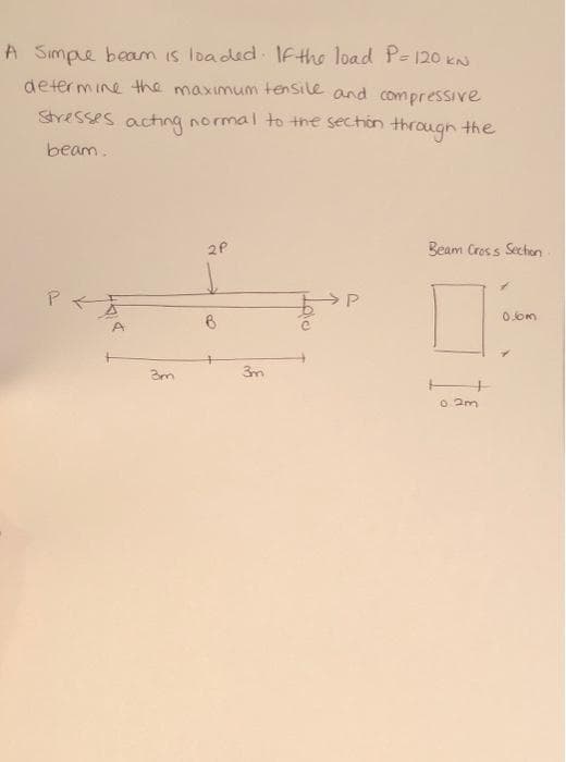
Transcribed Image Text:A Simpe beam is loaded IFthe load P= 120 kN
determine the maximum tensile and com pressive
Stresses acting normal to the section through the
beam.
2P
Beam Cross Section
P-天
0.0m
A.
3m
O 2m
Expert Solution
This question has been solved!
Explore an expertly crafted, step-by-step solution for a thorough understanding of key concepts.

Step by step
Solved in 3 steps with 3 images

Knowledge Booster


Learn more about
Need a deep-dive on the concept behind this application? Look no further. Learn more about this topic, mechanical-engineering and related others by exploring similar questions and additional content below.Recommended textbooks for you
Mechanics of Materials (MindTap Course List)
Mechanical Engineering
ISBN:
9781337093347
Author:
Barry J. Goodno, James M. Gere
Publisher:
Cengage Learning
Mechanics of Materials (MindTap Course List)
Mechanical Engineering
ISBN:
9781337093347
Author:
Barry J. Goodno, James M. Gere
Publisher:
Cengage Learning