A simply supported beam hinged at A and supported at C, is carrying a distributed load and a point load (see Fig. 1). The beam has a Young Modulus E = 80 GPa and a constant depth of 400 mm. The moment of inertia of the beam is limited to be I = 255 x 10-4 m*. P- 120 KN 9. 15 KN/m 4 On Figure 1 (a) (0 Write the bending moment expression using Macauley's method. (ii) Determine the bending moment at A. (ii) Determine the bending moment at B. (iv) Determine the bending moment at C.
A simply supported beam hinged at A and supported at C, is carrying a distributed load and a point load (see Fig. 1). The beam has a Young Modulus E = 80 GPa and a constant depth of 400 mm. The moment of inertia of the beam is limited to be I = 255 x 10-4 m*. P- 120 KN 9. 15 KN/m 4 On Figure 1 (a) (0 Write the bending moment expression using Macauley's method. (ii) Determine the bending moment at A. (ii) Determine the bending moment at B. (iv) Determine the bending moment at C.

Mechanics of Materials (MindTap Course List)
9th Edition
ISBN:9781337093347
Author:Barry J. Goodno, James M. Gere
Publisher:Barry J. Goodno, James M. Gere
Chapter9: Deflections Of Beams
Section: Chapter Questions
Problem 9.5.1P: A simply supported beam (E = 1600 ksi) is loaded by a triangular distributed load from A to C(see...

Related questions
Question
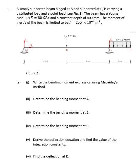
Transcribed Image Text:A simply supported beam hinged at A and supported at C, is carrying a
distributed load and a point load (see Fig. 1). The beam has a Young
Modulus E = 80 GPa and a constant depth of 400 mm. The moment of
inertia of the beam is limited to be I = 255 x 10-4 m*.
1.
P- 120 KN
9 15 KN/m
4 (m)
2 (m)
Figure 1
(a) (i) Write the bending moment expression using Macauley's
method.
(ii) Determine the bending moment at A.
(ii) Determine the bending moment at B.
(iv) Determine the bending moment at C.
(v) Derive the deflection equation and find the value of the
integration constants.
(vi) Find the deflection at
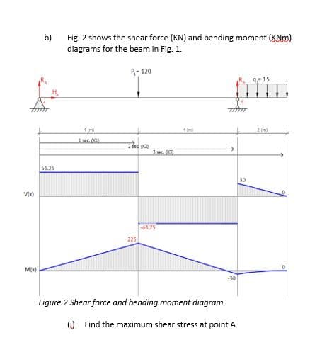
Transcribed Image Text:b)
Fig. 2 shows the shear force (KN) and bending moment (KNm)
diagrams for the beam in Fig. 1.
P- 120
9- 15
4 (m
2 (m)
3 sec. 3)
56.25
30
63.75
225
Mx)
Figure 2 Shear force and bending moment diagram
(i) Find the maximum shear stress at point A.
Expert Solution
This question has been solved!
Explore an expertly crafted, step-by-step solution for a thorough understanding of key concepts.

Step by step
Solved in 2 steps with 2 images

Knowledge Booster


Learn more about
Need a deep-dive on the concept behind this application? Look no further. Learn more about this topic, mechanical-engineering and related others by exploring similar questions and additional content below.Recommended textbooks for you
Mechanics of Materials (MindTap Course List)
Mechanical Engineering
ISBN:
9781337093347
Author:
Barry J. Goodno, James M. Gere
Publisher:
Cengage Learning
Mechanics of Materials (MindTap Course List)
Mechanical Engineering
ISBN:
9781337093347
Author:
Barry J. Goodno, James M. Gere
Publisher:
Cengage Learning