
Videos
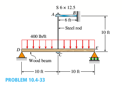
The cantilever beam AB shown in the figure is an S6 × 12.5 steel I-beam with E = 30 × 106 psi. The simple beam DE is a wood beam 4 in. x 12 in. (nominal dimensions) in cross section with E = 1.5 x 10⁶ psi. A steel rod AC of diameter 0.25 in., length 10 ft, and E = 30 x 106 psi serves as a hanger joining the two beams. The hanger fits snugly between the beams before the uniform load is applied to beam DE.
Determine the tensile force Fin the hanger and the maximum bending moments MABand MDEin the two beams due to the uniform load, which has an intensity q = 400 lb/ft. Hint: To aid in obtaining the maximum bending moment in beam DE, draw the shear-force and bending-moment diagrams.

Trending nowThis is a popular solution!

Chapter 10 Solutions
Mechanics of Materials (MindTap Course List)


- A propped cantilever beam of length L = 54 in. with a sliding support supports a uniform load of intensity q (see figure). The beam is made of steel {<7y = 36 ksi) and has a rectangular cross section of width/) = 4.5 in. and height h = 6.0 in. What load intensity q will produce a fully plastic condition in the beam?arrow_forwardA cantilever beam AB of length L = 6 It is constructed of a W 8 x 21 wide-flange section (see figure), A weight W = 1500 lb falls through a height h = 0.25 in. onto the end of the beam. Calculate the maximum deflection £m.iy of the end of the beam and the maximum bendini* stress *rm,vdue to the falling weight, (Assume E = 30 X 10 psi,)arrow_forwardA simple beam that is 18 ft long supports a uniform load of intensity q. The beam is constructed of two C8 x 11.5 sections (channel sections or C-shapes) on either side of a 4 × 8 (actual dimensions) wood beam (see the cross section shown in the figure part a). The modulus of elasticity of the steel (E; = 30,000 ksi) is 20 times that of the wood (Ew). (a) If the allowable stresses in the steel and wood are 12,000 psi and 900 psi, respectively, what is the allowable load qmax Note: Disregard the weight of the beam, and see Table F-3(a) of Appendix F for the dimensions and properties of the C-shape beam. (b) If the beam is rotated 90° to bend about its v axis (see figure part b) and uniform load q = 250 lb/ft is applied, find the maximum stresses trs and crw in the steel and wood, respectively Include the weight of the beam. (Assume weight densities of 35 lb/ft3 and 490 lb/ft3 for the wood and steel, respectively.)arrow_forward
- A cantilever beam AB of length L = 6.5 ft supports a trapezoidal distributed load of peak intensity 4, and minimum intensity q/2tthat includes the weight of the beam (see figure). The beam is a steel W 12 × 14 wide-flange shape (see Table F-l(a), Appendix F). Calculate the maximum permissible load q based upon (a) an allowable bending stress eallow = 18 ksi and (b) an allowable shear stress eallow = 7,5 ksi. Note: Obtain the moment of inertia and section modulus of the beam from Table F-l(a).arrow_forwardThe hollow box beam shown in the figure is subjected to a bending moment M of such magnitude that the flanges yield but the webs remain linearly elastic. (a) Calculate the magnitude of the moment M if the dimensions of the cross section are A = 15 in., A] = 12.75 in., h = 9 in., and ey =7.5 in. Also, the yield stress is eY = 33 ksi. (b) What percent of the moment M is produced by the elastic core?arrow_forwardA beam with a guided support and 10-ft span supports a distributed load of intensity q = 660 lb/ft over its first half (see figure part a) and a moment Mq = 300 ft-lb at joint B. The beam consists of a wood member (nominal dimensions 6 in. x 12 in. and actual dimensions 5.5 in. x 11.5 in. in cross section, as shown in the figure part b) that is reinforced by 0.25-in.-thick steel plates on top and bottom. The moduli of elasticity for the steel and wood are £s = 30 X 106 psi and £"w = 1.5 X 10⁶ psi, respectively. Calculate the maximum bending stresses trs in the steel plates and rw in the wood member due to the applied loads. If the allowable bending stress in the steel plates is = 14,000 psi and that in the wood is (T.dV!= 900 psi, find qmiiX. (Assume that the moment at .fi, A/0, remains at 300 ft-lb.) If q = 660 lb/ft and allowable stress values in part (b) apply, what is Müm^ at B?arrow_forward
- A hollow box beam with height h = 16 in,, width h = 8 in,, and constant wall thickness r = 0.75 LiL is shown in the figure. The beam is constructed of steel with yield stress ty = 32 ksi. Determine the yield moment My, plastic moment A/p, and shape factor.arrow_forwardA hollow box beam with height h = 9.5 in., inside height/i, = 8.0 in., width? = 5,25 in., and inside width =4.5 in. is shown in the figure. Assuming that the beam is constructed of steel with yield stress ty= 42 ksi calculate the yield moment My, plastic moment MPand shape factor f.arrow_forwardA simple beam with a W 10 x 30 wide-flange cross section supports a uniform load of intensity q = 3.0 kips/ft on a span of length L = 12 ft (sec figure). The dimensions of the cross section are q = 10.5 in., b = 5.81 in., t1= 0.510 in., and fw = 0.300 in. Calculate the maximum shear stress tjuly on cross section A—A located at distance d = 2.5 ft from the end of the beam. Calculate the shear stress rat point Bon the cross section. Point B is located at a distance a = 1.5 in. from the edge of the lower flange.arrow_forward
- -14 A simply supported composite beam with a 3.6 m span supports a triangularly distributed load of peak intensity q0at mid-span (see figure part a). The beam is constructed of two wood joists, each 50 mm x 280 mm, fastened to two steel plates, one of dimensions 6 mm × 80 mm and the lower plate of dimensions 6 mm x 120mm (see figure part b). The modulus of elasticity for the wood is 11 GPa and for the steel is 210 GPa. If the allowable stresses are 7 MPa for the wood and 120 MPa for the steel, find the allowable peak load intensity q0maxwhen the beam is bent about the z axis. Neglect the weight of the beam.arrow_forwardBeam ACB hangs from two springs, as shown in the figure. The springs have stiffnesses Jt(and k2^ and the beam has flexural rigidity EI. What is the downward displacement of point C, which is at the midpoint of the beam, when the moment MQis applied? Data for the structure are M0 = 7.5 kip-ft, L = 6 ft, EI = 520 kip-ft2, kx= 17 kip/ft, and As = 11 kip/ft. Repeat part (a), but remove Af0 and instead apply uniform load q over the entire beam.arrow_forwardA cantilever beam with a uniform load (see figure) has a height h equal to 1/8 of the length L. The beam is a steel wide-flange section with E = 28 X 106 psi and an allowable bending stress of 17,500 psi in both tension and compression. Calculate the ratio S/L of the deflection at the free end to the length, assuming that the beam carries the maximum allowable load. (Use the formulas of Example 9-2.)arrow_forward
 Mechanics of Materials (MindTap Course List)Mechanical EngineeringISBN:9781337093347Author:Barry J. Goodno, James M. GerePublisher:Cengage Learning