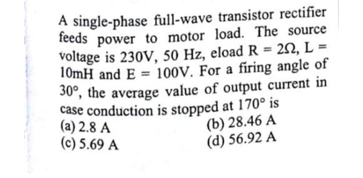
A single-phase full-wave transistor rectifier power to motor load. The source feeds voltage is 230V, 50 Hz, eloadR = 22, L 10mH and E = 100V. For a firing angle of 30", the average value of output current in case conduction is stopped at 170° is (a) 2.8 A (c) 5.69 A %3D %3D %3D (b) 28.46 A (d) 56.92 A


Q: Determine the peak output voltage for the bridge rectifier in this figure. Assuming the practical…
A: The given bridge rectifier is, The model is practical and Voltage at Transformer's primary,…
Q: what is the peak voltage of the input signal (Vp)?
A:
Q: Setup the Half Wave Rectifier using LiveWire Simulation software for the given below values. f=1HZ…
A:
Q: Explain the firing angle range in the half-wave and full-wave controlled rectifier circuits feeding…
A: The solution is mentioned below
Q: Ql: A half-controlled three-phase bridge rectifier is supplied at 220 V (RMS line voltage) from a…
A: A rectifier circuit is used to rectify the AC power generated by this source to the DC power that…
Q: A single-phase full-wave transistor rectifier power to motor load. The source feeds voltage is 230V,…
A: In this question we need to find average output current of given rectifier.
Q: A 4:1 transformer is connected to a bridge rectifier circuit with a lkn load. What is the peak…
A:
Q: A single-phase full-wave controlled rectifier is supplied from a 220V, 50HZ source and has an RL…
A:
Q: A conductor carries a current that is equivalent to a 5-amp continuous current in one direction and…
A: In a full wave rectifier that convert the complete cycle of AC into a pulsating Direct current. It…
Q: Determine the peak output voltage for the bridge rectifier in this figure. Assuming the practical…
A:
Q: A number of diodes rated at 1620 V each are to be connected in series in a rectifier circuit with a…
A: According to the question we have to find the value, the number of diodes that must be used, a…
Q: A centre-tap full-wave rectifier (CT-FWR) is operated from a (60 Hz), (110 V,ms) line voltage…
A: Thank you for the question. Your question consist of multiple sub-parts, as per company policy I…
Q: A R-load half-wave rectifier used sinusoidal voltage source with a peak value (35.353kV). The firing…
A:
Q: By comparing the performance of DC -DC chopper with controlled rectifier circuit, which one of the…
A: In this question we need to choose a correct option.
Q: A PMMC instrument with FSD = 50µA and Rm =2.2k2 is to be employed as an ac voltmeter with FSD=220V…
A: The basic circuit for enhancement of voltmeter is as shown below:
Q: A half-wave rectifier haS an input voltage of 120 Vrms at 60 Hz and requires a maximum voltage…
A: Forward biasing of a diode: When applied voltage increases repulsion forces to the majority carriers…
Q: What value of filter capacitor is required to produce 1% ripple factor for a full-wave rectifier…
A: Given data, Ripple factor, r = 1% = 0.01. Load resistance, RL = 1.5 kΩ=1500 Ω. Load voltage, VL =…
Q: Is it possible to construct rectifier circuits by MOSFET? Justify. ( short anser only plases )
A: It is possible to create a very efficient rectifier with a MOSFET - but not by just connecting the…
Q: Consider the half wave rectifier is supplied with 115V, 80HZ signal. Assume the number of turns in…
A:
Q: Suppose a power supply is energized by an AC source of 119 V RMS. The transformer step-down ratio is…
A: Given: Full wave transformer step down amplifier
Q: Single-phase uncontrolled (diode) bridge rectifier is supplied by 220 V, 50 Hz AC voltage. DC load…
A: For uncontrolled bridge rectifier the input current harmonics will be mainly due to the fundamental…
Q: In an electronic laboratory, a diode rectifier tube has a plate resistance of 500 ohms (assumed…
A: In the question a half wave diode rectifier is given which is connected to Load 1500 ohms and diode…
Q: A 60-Hz full-wave rectifier is built with a transformer having an rms secondary voltage of 20 V and…
A: Given: To find the largest current that supplied by the rectifier which is less than 0.3 V is shown…
Q: a. Calculate the transistor's Emitter current if it is driven by a small Base current of 7mA with a…
A: Here is a transistor is given so first write the relation between emitter collector and base current…
Q: Q1) In the transformer-coupled filter-bridge circuit shown, the va the transformer secondary voltage…
A: Single phase full wave rectifier- In single-phase, full converter due to the negative voltage spice…
Q: A particular load has to be supplied with an average power of 50mW, 5V dc voltage. Find the value of…
A: The given information about a half wave rectifier with capacitor filter. The average output power…
Q: The gate current of an SCR full-wave rectifier is adjusted to 1.2mA and the forward breakdown…
A: Given gate current of 1.2 mA and corresponding break over voltage is 150 volts so scr starts…
Q: A rectifier type AC voltmeter consists of a series resistance R, an ideal full-wave rectifier bridge…
A: PMMC Voltmeter The permanent magnet moving coil type voltmeter is a voltage measuring instrument…
Q: A classical rectifier is to be designed to provide 5V ± 1% for a logic circuit, with output power of…
A: Given,Output power, Pout=12WInput voltage, Vin=220VFrequency, f=50HzOutput voltage, Vout=5V±1%
Q: A three-phase controlled rectifier is supplied from a 400V, 50HZ line and supplying an RLE load with…
A:
Q: A full-wave peak rectifier is supplied by a 50-Hz ac source having a peak value, Vp = 30V. The value…
A:
Q: A classical rectifier is to be designed to provide 5V 1% for a logic circuit, with output power of…
A: A diode is a two-terminal one-way switch, it will only allow the flow of current in one direction,…
Q: Q5- A three-phase controlled rectifier is supplied from a 415V, 50Hz line and supplying an RLE load…
A: “Since you have posted a question with multiple sub-parts, we will solve first three sub-parts for…
Q: A circuit of 3-Phase Controlled Half Wave Rectifier with Resistive load is as below. eeceecee If the…
A: Three phase half controlled rectifier with restive load α=π9=200 Vrms=208 V phase Assumptions 1) We…
Q: For unipolar PWM switching, assume a positive load current (io > 0). Which combinations of switches…
A: Given circuit is full; bridge inverter. It can operate in unipolar PWM mode or Bipolar PWM mode.
Q: + (a) Define external efficiency of an LED and how this efficiency can be increased. (b) With the…
A: Given We need to enumerate about external efficiency of LED. Please find the below attachment for…
Q: The power of an 80 Watt, 220V lamp is to be varied by controlling the firing angle of an SCR in a…
A: In the given question we note that The power of an 80 Watt, 220 v lamp is varied by controlling the…
Q: Q6 A phase-controlled six-pulse rectifier is fed from a 460-V, 60-Hz line, supplies an RLE load, of…
A: Given :Vm=460 Vf=60 HzR=0.3 ΩL=1.7 mH
Q: A full-wave bridge rectifier is operated from a (50 Hz), (220 Vrms) line voltage. It has a (100 µF)…
A: Dear student as per our guidelines we are supposed to solve only one question in which it should…
Q: A simple diode rectifier has 'ripples' in the output wave which makes it unsuitable as a DC source.…
A:
Q: A silicon controlled rectifier (SCR) has a forward breakdown voltage of 230 V. When a gate current…
A:
Q: A conductor carries a current that is equivalent to a 2.5 amp continuous current in one direction…
A: Given, that the conductor carries a Dc-current of 2.5 A in one direction & a super-imposed…
Q: 8. What value of filter capacitor is required to produce 1% ripple factor for a full-wave rectifier…
A: We need to find a capacitor to limit the ripple to 1%
Q: half-wave rectifier circuit employing an SCR is adjusted to have a gate current of 10mA
A:
Q: A full-wave bridge rectifier is operated from a (50 Hz), (220 Vms) line µF) filter capacitor and (1…
A: Since we only add up to 3 subparts, we will answer the first 3. Please resubmit the question and…
Q: ER VO Sa ac ine Itage
A: Hello. Since your question has multiple sub-parts, we will solve the first three sub-parts for you.…
Q: 8-The waveform of output voltage of half-controlled three phase bridge rectifier in each cycle…
A: Rectifiers are used to convert the AC signal to DC signal.it can be controlled as well as…
Q: A centre-tap full-wave rectifier (CT-FWR) is operated from a (60 Hz), (110 Vrms) line voltage…
A: Thank you for the question. Your question consist of multiple sub-parts, as per company policy I…
Q: Design a CT-FWR to supply a load of (500) with a waveform of the following specifications: - • Vde =…
A: In this question we will find FWR parameters... Note:- due to bartleby policy, I will answer first 3…
Q: Design rectifier circuits to provide an output of 100 VDc using a) HWR and b) Center-tapped FWR…
A: A rectifier is an AC to DC converter. The rectifier converts AC voltage into pulsating DC Voltage.…

Step by step
Solved in 2 steps with 1 images


- A 60-Hz full-wave rectifier is built with a transformer having an rms secondary voltage of 20 V and filter capacitance C =150,000 μF. What is the largest current that can be supplied by the rectifier circuit if the ripple must be less than 0.3 V?A schematic design of a full-wave bridge type power supply is given below. Provide the appropriate values for the inductors, diodes, capacitor and resistors, such that the output DC voltage is 6.2 V and the max. output power for the load resistance is 20 mW (percentage error for output voltage and output power is 2%). AC voltage source: Amplitude=311.13, Freq=60, DC offset= 0. For the rectifier part, choose diodes with an appropriate PIV rating. Show all the formulas and computations involved in acquiring the values for the inductors, diodes, capacitor and resistors. In choosing your Zener diode, consider the output voltage and the output current. Note that the output current should be the minimum Zener current. For the value of the series resistor RS, choose a lower value for less ripple but always consider the required output voltage. The ripple voltage peak-to-peak value should be less than or equal to 1% of the required output voltage. Use the formula below for choosing the value…In the figure, SCR semiconductor switched rectifier to a 220 Vrms ac source at 50 Hz, at load Vdc = 100 V, R = 8 Ω and has an inductor large enough to supply continuous current. (a) Trigger angle α = 25o determine the total power absorbed by the load. (b) If the inductance value is 30 mH, the change value from the top Determine.
- Design a CT-FWR to supply a load of (50) with a waveform of the following specifications: - Vdc = 12 V Ripple factor = 0.1 % the main power supply is (220 Vrms, 50 Hz). Determine the following values: - 1- The value of capacitor filter. 2- The maximum load voltage (VmR) 3- The transformer turns ratio (a). 4- The RMS value of the load voltage. 5- Draw the output waveform. (assume ideal diodes)A step-down transformer supplies 25Vrms to a simple half wave rectifier power supply which is connected to a load resistance of 912ohm. The diode breakdown voltage, Vf is 0.7 V. Calculate the peak signal voltage received by the diodeDesign a full-wave bridge type power supply. Design the transformer, filter and regulator section. For the rectifier part, choose diode with appropriate PIV rating. Use standard values for your design. The output dc voltage should be 7.5 V and the Maximum output power be 20 mW. Use the topology below as reference
- A half-wave rectifier is needed to supply 15-V dc to a load that draws an average current of 250 mA. The peak-to-peak ripple is required to be 0.2 V or less. What is the minimum value allowed for the smoothing capacitance? If a full-wave rectifier is needed?The voltage waveforms shown below are obtained from a three-phase power rectifier used in an ESKOM application.The rectifier output before the inductive filter is denoted by VL and the load voltage after the inductive filter by Vo. Ignore any diode losses and consider a load resistance of 12.7 Ω. Analyse the waveforms and specify / calculate,11) the supply frequency;12) the rectifier pulse number;13) the rectifier average output voltage;14) the average output current;15) the r.m.s. value of the output current;16) the r.m.s. value of the harmonics present in the output current;17) the dc current rating of the rectifier diodes;18) the r.m.s. current rating of the rectifier diodes;19) the peak repetitive reverse voltage rating of the rectifier diodes;20) the peak repetitive forward current rating of the rectifier diodes;21) the line-line r.m.s. voltage of the three-phase supply;22) the rectification efficiency of the converter;23) the converter transformer utilisation factor;During output power measurement DC gives a deflection whereas AC gives properoutput. Why? Explain it. (Voltmeter, Ammeter and Isolator Connection of a Simple Half Wave Rectifier Circuit.)
- Design a circuit for an uncontrolled half-wave Rectifier based transformer step down containing a capacitor filter circuit, with writing the laws of the circuit and the shape of the output wave, with a comparison between the current output wave and the voltage output wave in terms of being affected by the placement of the filter.4- What is the effect of adding capacitor in parallel to the load at the rectifier output? Note: Please do not handwriting and write the answer briefly. What value of filter capacitor is required to produce a 1% ripple factor for a full-wave rectifier havinga load resistance of 1.5 kΩ? Assume the rectifier produces a peak output of 18 V.