A single-phase full-wave transistor rectifier power to motor load. The source feeds voltage is 230V, 50 Hz, eload R = 2N, L = 10mH and E = 100V. For a firing angle of 30, the average value of output current in case conduction is stopped at 170° is (a) 2.8 A (c) 5.69 A %3D %3D (b) 28.46 A (d) 56.92 A
A single-phase full-wave transistor rectifier power to motor load. The source feeds voltage is 230V, 50 Hz, eload R = 2N, L = 10mH and E = 100V. For a firing angle of 30, the average value of output current in case conduction is stopped at 170° is (a) 2.8 A (c) 5.69 A %3D %3D (b) 28.46 A (d) 56.92 A

Delmar's Standard Textbook Of Electricity
7th Edition
ISBN:9781337900348
Author:Stephen L. Herman
Publisher:Stephen L. Herman
Chapter30: Dc Motors
Section: Chapter Questions
Problem 6RQ: What is CEMF?

Related questions

Question
N1
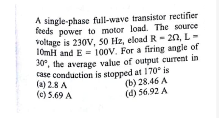
Transcribed Image Text:A single-phase full-wave transistor rectifier
feeds power to motor load. The source
voltage is 230V, 50 Hz, eload R = 20, L =
10mH and E = 100V. For a firing angle of
%3D
%3D
30, the average value of output current in
case conduction is stopped at 170° is
(a) 2.8 A
(c) 5.69 A
(b) 28.46 A
(d) 56.92 A
Expert Solution
This question has been solved!
Explore an expertly crafted, step-by-step solution for a thorough understanding of key concepts.

Step by step
Solved in 2 steps with 1 images

Knowledge Booster


Learn more about
Need a deep-dive on the concept behind this application? Look no further. Learn more about this topic, electrical-engineering and related others by exploring similar questions and additional content below.Recommended textbooks for you
Delmar's Standard Textbook Of Electricity
Electrical Engineering
ISBN:
9781337900348
Author:
Stephen L. Herman
Publisher:
Cengage Learning
Delmar's Standard Textbook Of Electricity
Electrical Engineering
ISBN:
9781337900348
Author:
Stephen L. Herman
Publisher:
Cengage Learning