(a) The reaction forces at the two ends of the shaft A and D. (b) The bending moments at shoulder fillets B and C. (c) The nominal stresses at shoulder fillets B and C.
(a) The reaction forces at the two ends of the shaft A and D. (b) The bending moments at shoulder fillets B and C. (c) The nominal stresses at shoulder fillets B and C.

Mechanics of Materials (MindTap Course List)
9th Edition
ISBN:9781337093347
Author:Barry J. Goodno, James M. Gere
Publisher:Barry J. Goodno, James M. Gere
Chapter3: Torsion
Section: Chapter Questions
Problem 3.3.15P: A hollow steel shaft used in a construction auger has an outer diameter d2= 6.0 in. and inner...

Related questions

Question
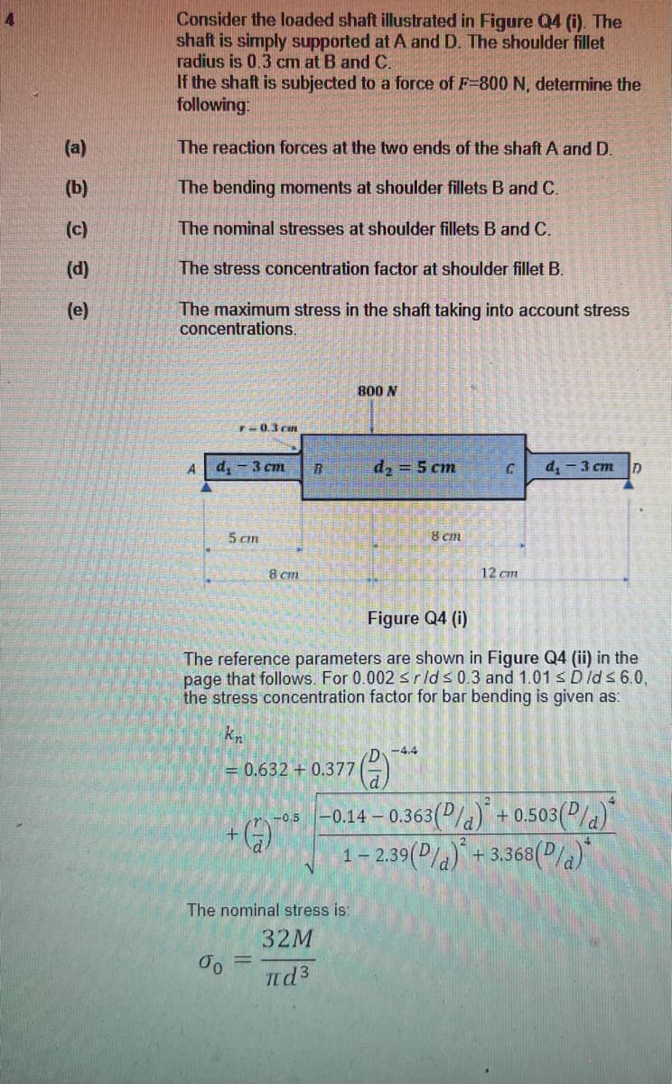
Transcribed Image Text:Consider the loaded shaft illustrated in Figure Q4 (i). The
shaft is simply supported at A and D. The shoulder fillet
radius is 0.3 cm at B and C.
If the shaft is subjected to a force of F-800 N, determine the
following:
(a)
The reaction forces at the two ends of the shaft A and D.
(b)
The bending moments at shoulder fillets B andC.
(c)
The nominal stresses at shoulder fillets B and C.
(d)
The stress concentration factor at shoulder fillet B.
(e)
The maximum stress in the shaft taking into account stress
concentrations.
800 N
T-0.3 can
A
d, - 3 cm
d, = 5 cm
d, - 3 cm
5 cm
8 cm
8 cm
12 cm
Figure Q4 (i)
The reference parameters are shown in Figure Q4 (ii) in the
page that follows. For 0.002 srlds 0.3 and 1.01 s Dlds 6.0,
the stress concentration factor for bar bending is given as:
kn
-4.4
= 0.632 + 0.377
-0.14 – 0.363(P/a)" + 0.503(P/a)
1- 2.39(P/a) + 3.368(2la)*
-0.5
The nominal stress is:
32M
%3D
nd3
Expert Solution
This question has been solved!
Explore an expertly crafted, step-by-step solution for a thorough understanding of key concepts.

Step by step
Solved in 2 steps with 2 images

Knowledge Booster


Learn more about
Need a deep-dive on the concept behind this application? Look no further. Learn more about this topic, mechanical-engineering and related others by exploring similar questions and additional content below.Recommended textbooks for you
Mechanics of Materials (MindTap Course List)
Mechanical Engineering
ISBN:
9781337093347
Author:
Barry J. Goodno, James M. Gere
Publisher:
Cengage Learning
Mechanics of Materials (MindTap Course List)
Mechanical Engineering
ISBN:
9781337093347
Author:
Barry J. Goodno, James M. Gere
Publisher:
Cengage Learning