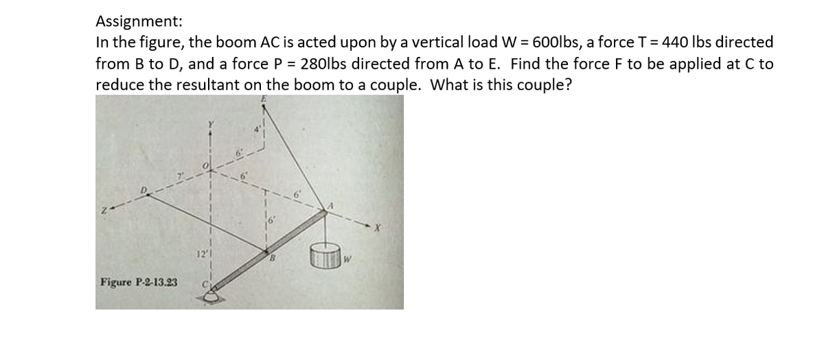
Assignment: In the figure, the boom AC is acted upon by a vertical load W = 600lbs, a force T= 440 lbs directed from B to D, and a force P = 280lbs directed from A to E. Find the force F to be applied at C to reduce the resultant on the boom to a couple. What is this couple? 12'1 Figure P-2-13.23
Q: A curved bar BCDE is shown in the figure with origin of the reference axes at E. A force F⃗1 equal…
A:
Q: The overhanging beam is supported by a pin at A and the two-force strut BC as shown in Figure Q4.1.…
A: Draw the FBD of the given question and find the angle between the horizontal line and the member BC.
Q: B Support reactions will be found in the gerber beam whose loading condition is given in the figure.…
A:
Q: La7 For the simply supported beam and the loading shown in the figure find the * Chinge forces (B)…
A: It is required to determine support reaction force
Q: F = 5.2 i +3 J Q5/ Compute the magnitude of force (F) and the X. vertical reaction at point (A) of…
A: 5. F=5.2i+3j...So, Magnitude of F=5.22+32=6 From the equilibrium equation by ∑Fy=0 Ay-3=0... So,…
Q: The overhanging beam is supported by a pin at A and the two-force strut BC as shown in Figure Q4.1.…
A:
Q: The embedded cone of height h and circular base (radius R) in the figure is subjected to the strut…
A: Axial force, shear forces, bending moments and torsional moments due to the loading needs to be…
Q: The simply supported beam in the figure is loaded by the counterclockwise Co at B. Draw the shear…
A: To draw SFD and BMD
Q: Consider the following FBD of bar ABC with the pulleys included Write the moment equation M…
A: Given data To determine the moment equation of link ABC.
Q: In the figure, one end of a uniform beam of weight 440 N is hinged to a wall; the other end is…
A: Consider the FBD as shown below.
Q: In figure, there is a single rigid beam supported at two points: A and B. 250 N 2 m Calculate the…
A:
Q: 4.3-10 Under cruising conditions, the distributed load aeting on the wing of a small airplane has…
A:
Q: 4.3-20 A space truss is supported at O, A, D, and C (see figure). Loads P are applied in the y…
A:
Q: 2. a) Compute the resultant force for the loads shown in Figure 1 acting on the cantilever. What…
A: A pin support will exert both horizontal and vertical components of reaction as the reaction forces.…
Q: For the rod loaded as shown in figure, the maximum bending moment is 5 kN-m. AB=BC=CD= 1m. The value…
A: The bending moment due to force of 2 kN can be determined as,
Q: 3. Find all the support reactions A and N and also calculate all the internal forces in the truss…
A: Given Data use theorem of zero force membersIn a given point, If 3 members are meeting, with one…
Q: In the figure, one end of a uniform beam of weight 340 N is hinged to a wall; the other end is…
A:
Q: he overhang beam shown in Figure Q2 is pinned at A and rest on a roller at B. The eam supports a…
A:
Q: The beam ABC shown in the figure is simply supported at A and B and has an overhang from B to C. The…
A:
Q: SITUATION 2 A riveted bracket show in the figure is subjected to load P acting at an angle of e from…
A:
Q: A 15,000 N crane pivots around a friction-free axle at its base and is supported by a cable making a…
A: a.
Q: The steel structure in the figure is supported at point B, but the support is not shown. Parts ABCD…
A:
Q: A flanged wooden shape is used to support the loads shown on the beam. The dimensions of the shape…
A:
Q: 18 kN A AZ 2 m 4 m B
A:
Q: A beam (AB) is attached to a roller at A and a pin at B. It is subjected to three concentrated…
A: Given data beam (AB) is attached to a roller at A and a pin at B. It is subjected to three…
Q: 4.5-6 The simple beam AB shown in the figure is subjected to a concentrated load P and a clockwise…
A:
Q: Question Bank- Moments Three forces F1, F2, and F3 are applied to a beam as shown in the figure.…
A:
Q: Practice Problem 2.4.1: The three P3 = 60 kN P3 = 80 kN P = 25 kN forces acting on the beam can be…
A: Take moment about P3 P2sinθ6+P1sin4010=060sinθ6=-25sin4010θ=-26.51° Total forces…
Q: Express shear force V and bending moment M as functions of arbitrary position x along the axis for…
A:
Q: Problem 1. For the frame shown in the figure, determine (a) Reactions at the supports (b) Axial…
A: a) At equilibrium, Taking moment about A, ∑MA=0 -8×5-12×322-25×3-30×7.5-12×15-10×7+12VF=0VF=53.67 N…
Q: Calculate the shear force Vand bending moment Mata cross sectionjust to the right of the 800 lb load…
A:
Q: In the figure, one end of a uniform beam of weight 130 N is hinged to a wall; the other end is…
A:
Q: For the figure shown in the figure below. Find the Location of Zero Shear force and the maximum…
A:
Q: 2: For the beam shown in Fig.(2), find the reaction forces at supports A and B respectively? %) 20…
A:
Q: Replace the loading acting on the beam by an equivalent resultant force FR and couple moment (MR)C…
A:
Q: 3. Determine the normal force, shear force, and moment at a section thre ugh point C.Take B 0.1' m…
A:
Q: In the figure, one end of a uniform beam of weight 130 N is hinged to a wall; the other end is…
A: To find: The tension in the wire. Given: The weight of the one end of the beam is hinged to the wall…
Q: The overhanging beam is supported by a pin at A and the two-force strut BC as shown in Figure Q4.1.…
A: Now draw the free body diagram for the above problem.
Q: the reference axes at E. A force F⃗1 equal to 12 kN is applied parallel to the y-axis at point B. A…
A:
Q: Q4. A freely supported light uniform beam of length 8 metres is subject to the loading shown in…
A: For solution refer below images.
Q: h CORTE a-a clamp shown in the figure exerts a npressive force of 2.93 kN on the wooden cks.…
A: The maximum normal stress: + 597.144 MPa (Tensile @ bottom) - 597.144 MPa (Compressive @ Top)
Q: A flanged wooden shape is used to support the loads shown on the beam. The dimensions of the shape…
A:
Q: Consider the overhang beam shown in (Figure 1). Suppose that P = 7 kN , M = 6 kN⋅m , w = 4 kN/m .…
A:
Q: Question 1) For the beam whose loading condition is given in the figure, the force F is F = 18 kN,…
A: Free Body diagram of the beam Angle for inclined force F=18 kN sinθ=45θ=sin-1(45)θ=53.13o
Q: A beam (AB) is attached to a roller at A and a pin at B. It is subjected to three concentrated…
A:
Q: The beam AB shown in the figure supportsa uniform load of intensity 3000 N/m acting over halfthe…
A: At first drawing the beam AB as shown in the figure Here 3000Nm is the uniform load of intensity
Q: (2) Draw the shear force and bending moment diagrams for the beam ABCD shown in the figure below.…
A:
Q: Example The beam ABC is loaded via a 500 N.m couple and a 600 N force as shown. The beam is…
A:
Q: Find the support forces at Points A and B by showing the free body diagram in the simple beam given…
A: Convert the uniformly distributed load to a point load, P1=12 kN/m×4 m=48 kN Convert the uniformly…
Q: For the structural frame shown in figure (4), draw the axial, shear forces and bending moment…
A:
Trending now
This is a popular solution!
Step by step
Solved in 3 steps with 3 images
- Space Frame ABC is clamped at A, except it is free to rotate at A about the x and y axes. Cables DC and EC support the frame at C. Force Py= - 50 lb is applied at the mid-span of AS, and a concentrated moment Mx= -20 in-lb acts at joint B. (a) Find reactions at support A. (b) Find cable tension Forces.At a full d raw, an archer applies a pull of 130 N to the bowstring of the bow shown in the figure. Determine the bending moment at the midpoint of the bow.Find support reactions at A and D and then calculate the axial force N, shear force V, and bending moment M at mid-span of AB. Let L = 14 ft, q0 = 12 lb/ft, P = 50 lb. and = 300 lb-ft.
- A cable with force P is attached to a frame at D and runs over a frictionless pulley at A Find expressions for shear force V and moment M at x = L/3 of beam AB.A soccer goal is subjected to gravity loads (in the - z direction, w = 73 N/m for DG, BG, and BC; w = 29 N/m for all other members; see figure) and a force F = 200 N applied eccentrically at the mid-height of member DG. Find reactions at sup ports C, D, and H.A beam ABCD with a vertical arm CE is supported as a simple beam al A and D (see figure part a). A cable passes over a small pulley that is attached to the arm at E. One end of the cable is attached to the beam at point B. (a) What is the force P in the cable if the bending moment in the beam just lo the left of point C is equal numerically to 640 lb-ft? Note: Disregard the widths of the beam and vertical arm and use centerline dimensions when making calculations. (b) Repeat part (a) if a roller support is added at C and a shear release is inserted just left of C (see figure part b).
- Find expressions for shear force V and moment M at v = L/2 of beam AB in structure (a). Express V and M in terms of peak load intensity q0and beam length variable L. Repeat for structure (b) but find Fand M at m id-span of member BC.Space frame A BCD is clamped at A, except it is Free to translate in the .v direction. There is also a roller support at D, which is normal to line CDE. A triangularly distributed Force with peak intensity q0 = 75 N/m acts along AB in the positive - direction. Forces Px= 60 N and Pz = = 45 N are applied at joint C, and a concentrated moment My = 120 N . m acts at the mid-span of member BC. (a) Find reactions at supports A and I). (b) Find internal stress resultants N. E’I T, and .11 at the mid-height of segment AB.A cylindrical brick chimney of height H weighs w = 825 lb/ft of height (see figure). The inner and outer diameters are d1= 3 ft and d2= 4 ft, respectively. The wind pressure against the side of the chimney is p = 10 lb/ft2 of projected area. Determine the maximum height H if there is to be no tension in the brickwork.
- 1.3-15 A space truss is restrained at joints A, B, and C, as shown in the figure. Load 2P is applied at in the -x direction at joint A, load 3P acts in the + - direction at joint B. and load P is applied in the + r direction al joint C. Coordinates of all joints are given in terms of dimension variable L (see figure). (a) Find reaction force components Ayand Azin terms of load variable P. (b) Find the axial force in truss member AB in terms of load variable P.A large precast concrete panel for a warehouse is raised using two sets of cables at two lift lines, as shown in the figure part a. Cable 1 has a length L1 = 22 Ft, cable 2 has a length L2= 10 ft, and the distance along the panel between lift points Band D is d = 14 ft (see figure part b). The total weight of the panel is W = 85 kips. Assuming the cable lift Forces F at each lift line are about equal, use the simplified model of one half of the panel in figure part b to perform your analysis for the lift position shown. Find the required cross-sectional area AC of the cable if its breaking stress is 91 ksi and a factor of safety of 4 with respect to failure is desired.Find expressions for shear force V and moment M at x = x0of beam AB in terms of peak load intensity q0and beam length variable L. Let x0= 2L/3.