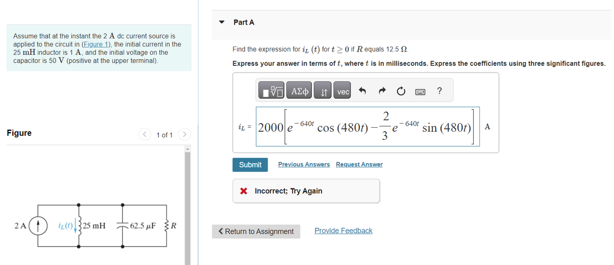
Assume that at the instant the 2 A dc current source is applied to the circuit in (Figure 1), the initial current in the 25 mH inductor is 1 A, and the initial voltage on the capacitor is 50 V (positive at the upper terminal). Figure 2A+ iL25 mH 1 of 1 62.5 μF R
Assume that at the instant the 2 A dc current source is applied to the circuit in (Figure 1), the initial current in the 25 mH inductor is 1 A, and the initial voltage on the capacitor is 50 V (positive at the upper terminal). Figure 2A+ iL25 mH 1 of 1 62.5 μF R

Introductory Circuit Analysis (13th Edition)
13th Edition
ISBN:9780133923605
Author:Robert L. Boylestad
Publisher:Robert L. Boylestad
Chapter1: Introduction
Section: Chapter Questions
Problem 1P: Visit your local library (at school or home) and describe the extent to which it provides literature...

Related questions
Question
100%
Please look carefully as the inputted answer appears to be incorrect.
Transcribed Image Text:Assume that at the instant the 2 A dc current source is
applied to the circuit in (Figure 1), the initial current in the
25 mH inductor is 1 A, and the initial voltage on the
capacitor is 50 V (positive at the upper terminal).
Figure
2A(1
iz(t) 325 mH
1325
1 of 1
62.5 μF R
Part A
Find the expression for it (t) for t≥ 0 if R equals 12.5 №.
Express your answer in terms of t, where t is in milliseconds. Express the coefficients using three significant figures.
-- ΑΣΦ ↓↑ vec
2
- 640t
iL 2000 e cos (480t) e
3
Submit
Previous Answers Request Answer
X Incorrect; Try Again
< Return to Assignment
Provide Feedback
640t
?
sin (480t) A
Expert Solution
This question has been solved!
Explore an expertly crafted, step-by-step solution for a thorough understanding of key concepts.

Step by step
Solved in 3 steps with 9 images

Knowledge Booster


Learn more about
Need a deep-dive on the concept behind this application? Look no further. Learn more about this topic, electrical-engineering and related others by exploring similar questions and additional content below.Recommended textbooks for you
Introductory Circuit Analysis (13th Edition)
Electrical Engineering
ISBN:
9780133923605
Author:
Robert L. Boylestad
Publisher:
PEARSON

Delmar's Standard Textbook Of Electricity
Electrical Engineering
ISBN:
9781337900348
Author:
Stephen L. Herman
Publisher:
Cengage Learning

Programmable Logic Controllers
Electrical Engineering
ISBN:
9780073373843
Author:
Frank D. Petruzella
Publisher:
McGraw-Hill Education
Introductory Circuit Analysis (13th Edition)
Electrical Engineering
ISBN:
9780133923605
Author:
Robert L. Boylestad
Publisher:
PEARSON
Delmar's Standard Textbook Of Electricity
Electrical Engineering
ISBN:
9781337900348
Author:
Stephen L. Herman
Publisher:
Cengage Learning
Programmable Logic Controllers
Electrical Engineering
ISBN:
9780073373843
Author:
Frank D. Petruzella
Publisher:
McGraw-Hill Education

Fundamentals of Electric Circuits
Electrical Engineering
ISBN:
9780078028229
Author:
Charles K Alexander, Matthew Sadiku
Publisher:
McGraw-Hill Education

Electric Circuits. (11th Edition)
Electrical Engineering
ISBN:
9780134746968
Author:
James W. Nilsson, Susan Riedel
Publisher:
PEARSON

Engineering Electromagnetics
Electrical Engineering
ISBN:
9780078028151
Author:
Hayt, William H. (william Hart), Jr, BUCK, John A.
Publisher:
Mcgraw-hill Education,