b) A fault occurs at bus 2 of the network shown in Figure Q3. Pre-fault nodal voltages throughout the network are of 1 p.u. and the impedance of the electric arc is neglected. Sequence impedance parameters of the generator, transmission lines, and transformer are given in Figure Q3, where X and Y are the last two digits of your student number. JX20)- /0.1X p.u. jX2 0.1X p.u. Xao)- J0.2Y p.u. %3D %3D V= 120° p.u. V 120° p.u. V, 120° p.u. jXa) /0.2X p.u. iXa2 j0.2X p.u. jX40) 0.2Y p.u. !! jXn)= 10.25 p.u. i A 2 Xng 0.25 p.u. 3 jXno)- j0.3 p.u. 0 X-70.2Y p.u. XT2- /0.2Y p.u. jXT1=70.2Y p.u. jXp)" J0.1X p.u. Xp- 0.1X p.u. Xo - /0.05 p.u. 0- %D !! 0. Figure Q3. Circuit for problem 3b). For example, if your student number is c1700123, then: jXa1) = j0.22 p.u., jXa(2) j0.22 p.u., and jXaco) = j0.23 p. u. %3D %3D (i) Assuming a balanced excitation, draw the positive, negative and zero (1) sequence Thévenin equivalent circuits as seen from bus 2. (i1) Determine the positive sequence fault current for the case when a three- phase-to-ground fault occurs at bus 2 of the network. (iii) Determine the short-circuit fault current for the case when a one-phase- to-ground fault occurs at bus 2.
b) A fault occurs at bus 2 of the network shown in Figure Q3. Pre-fault nodal voltages throughout the network are of 1 p.u. and the impedance of the electric arc is neglected. Sequence impedance parameters of the generator, transmission lines, and transformer are given in Figure Q3, where X and Y are the last two digits of your student number. JX20)- /0.1X p.u. jX2 0.1X p.u. Xao)- J0.2Y p.u. %3D %3D V= 120° p.u. V 120° p.u. V, 120° p.u. jXa) /0.2X p.u. iXa2 j0.2X p.u. jX40) 0.2Y p.u. !! jXn)= 10.25 p.u. i A 2 Xng 0.25 p.u. 3 jXno)- j0.3 p.u. 0 X-70.2Y p.u. XT2- /0.2Y p.u. jXT1=70.2Y p.u. jXp)" J0.1X p.u. Xp- 0.1X p.u. Xo - /0.05 p.u. 0- %D !! 0. Figure Q3. Circuit for problem 3b). For example, if your student number is c1700123, then: jXa1) = j0.22 p.u., jXa(2) j0.22 p.u., and jXaco) = j0.23 p. u. %3D %3D (i) Assuming a balanced excitation, draw the positive, negative and zero (1) sequence Thévenin equivalent circuits as seen from bus 2. (i1) Determine the positive sequence fault current for the case when a three- phase-to-ground fault occurs at bus 2 of the network. (iii) Determine the short-circuit fault current for the case when a one-phase- to-ground fault occurs at bus 2.

Power System Analysis and Design (MindTap Course List)
6th Edition
ISBN:9781305632134
Author:J. Duncan Glover, Thomas Overbye, Mulukutla S. Sarma
Publisher:J. Duncan Glover, Thomas Overbye, Mulukutla S. Sarma
Chapter9: Unsymmetrical Faults
Section: Chapter Questions
Problem 9.19P

Related questions
Question
X=2
Y=8
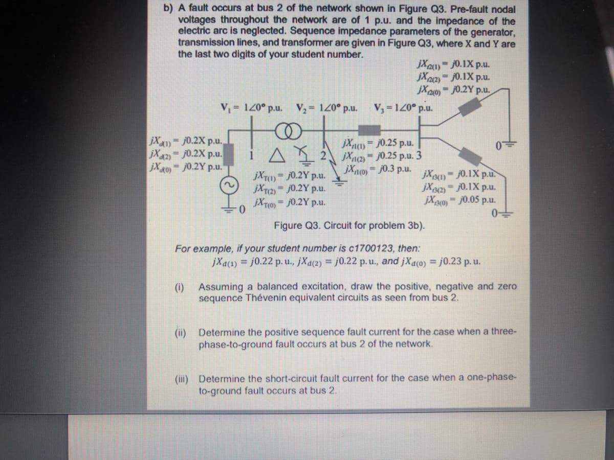
Transcribed Image Text:b) A fault occurs at bus 2 of the network shown in Figure Q3. Pre-fault nodal
voltages throughout the network are of 1 p.u. and the impedance of the
electric arc is neglected. Sequence impedance parameters
transmission lines, and transformer are given in Figure Q3, where X and Y are
the last two digits of your student number.
the generator,
JX20 0.1X p.u.
jXa
= j0.1X p.u.
Xaoy - J0.2Y p.u,
%3D
V, 120° p.u. V, 120° p.u.
V,-120° p.u.
jX4)-70.2X p.u.
Xn= /0.25 p.u.
i A1 2 Xae /0.25 p.u. 3
jXo)-j0.3 p.u.
Xaz
= j0.2X p.u.
jX40 /0.2Y p.u.
jXT0)-/0.2Y p.u.
jXr2 /0.2Y p.u.
jXT1 j0.2Y p.u.
jX) 0.1X p.u.
jX2 0.1X p.u.
jXpo) = J0.05 p.u.
Figure Q3. Circuit for problem 3b).
For example, if your student number is c1700123, then:
jXa1) = j0.22 p.u., jXa2) j0.22 p.u., and jXaco) = j0.23 p.u.
()
Assuming a balanced excitation, draw the positive, negative and zero
sequence Thévenin equivalent circuits as seen from bus 2.
(i)
Determine the positive sequence fault current for the case when a three-
phase-to-ground fault occurs at bus 2 of the network.
(iii) Determine the short-circuit fault current for the case when a one-phase-
to-ground fault occurs at bus 2.
Expert Solution
This question has been solved!
Explore an expertly crafted, step-by-step solution for a thorough understanding of key concepts.

Step by step
Solved in 5 steps with 5 images

Knowledge Booster


Learn more about
Need a deep-dive on the concept behind this application? Look no further. Learn more about this topic, electrical-engineering and related others by exploring similar questions and additional content below.Recommended textbooks for you
Power System Analysis and Design (MindTap Course …
Electrical Engineering
ISBN:
9781305632134
Author:
J. Duncan Glover, Thomas Overbye, Mulukutla S. Sarma
Publisher:
Cengage Learning
Power System Analysis and Design (MindTap Course …
Electrical Engineering
ISBN:
9781305632134
Author:
J. Duncan Glover, Thomas Overbye, Mulukutla S. Sarma
Publisher:
Cengage Learning