Consider a digital logic circuit with two diodes as shownin figure 1. The diodes D1 and D2 are ideal (i Vy = 0). 12 D out 10 D2 5V 50k2 Figure 1 A digital logic circuit with two ideal diodes A. Complete the equivalent circuit below and determine the output voltage vout oV and v, = 5V. Verify the conduction states of diodes by finding the current through D, and the voltage across D2 when vị = Note that the output voltage is the same when v, = 5V and v, = 0V. 12 D Fov out 12 D2 5V 50kn В. Complete the equivalent circuit below and determine the output voltage vout When vị = v2 = 5V. 12 D out 10 5V 50kn
Consider a digital logic circuit with two diodes as shownin figure 1. The diodes D1 and D2 are ideal (i Vy = 0). 12 D out 10 D2 5V 50k2 Figure 1 A digital logic circuit with two ideal diodes A. Complete the equivalent circuit below and determine the output voltage vout oV and v, = 5V. Verify the conduction states of diodes by finding the current through D, and the voltage across D2 when vị = Note that the output voltage is the same when v, = 5V and v, = 0V. 12 D Fov out 12 D2 5V 50kn В. Complete the equivalent circuit below and determine the output voltage vout When vị = v2 = 5V. 12 D out 10 5V 50kn

Power System Analysis and Design (MindTap Course List)
6th Edition
ISBN:9781305632134
Author:J. Duncan Glover, Thomas Overbye, Mulukutla S. Sarma
Publisher:J. Duncan Glover, Thomas Overbye, Mulukutla S. Sarma
Chapter4: Transmission Line Parameters
Section: Chapter Questions
Problem 4.2P: The temperature dependence of resistance is also quantified by the relation R2=R1[ 1+(T2T1) ] where...

Related questions
Question
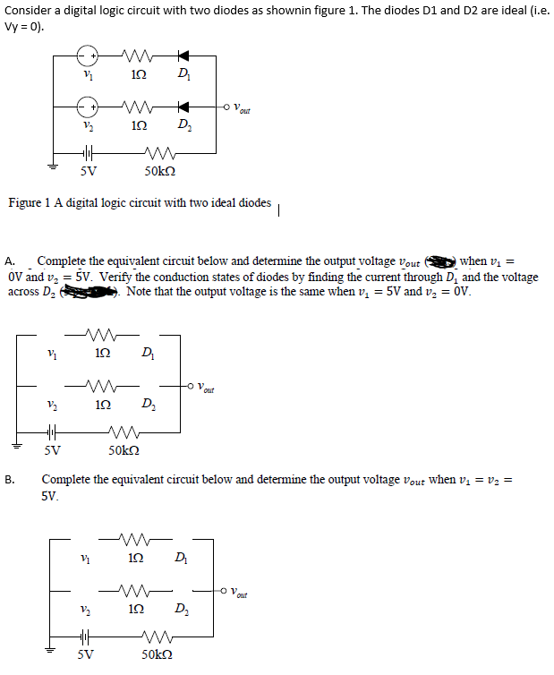
Transcribed Image Text:Consider a digital logic circuit with two diodes as shownin figure 1. The diodes D1 and D2 are ideal (i.e.
Vy = 0).
12
D
ov,
out
10
D2
5V
50kO
Figure 1 A digital logic circuit with two ideal diodes
A. Complete the equivalent circuit below and determine the output voltage vout
oV and v, = 5V. Verify the conduction states of diodes by finding the current through D, and the voltage
across D,
when vị =
Note that the output voltage is the same when v, = 5V and v, = 0V.
12
D
out
12
D2
5V
50k2
Complete the equivalent circuit below and determine the output voltage vout when vị = v2 =
В.
5V.
1Ω
D
Qut
10
5V
50k2
B.
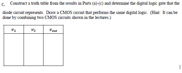
Transcribed Image Text:c. Construct a truth table from the results in Parts (a)-(c) and determine the digital logic gate that the
diode circuit represents. Draw a CMOS circuit that performs the same digital logic. (Hint: It can be
done by combining two CMOS circuits shown in the lectures.)
v1
v2
Vout
Expert Solution
This question has been solved!
Explore an expertly crafted, step-by-step solution for a thorough understanding of key concepts.

Step by step
Solved in 2 steps with 2 images

Knowledge Booster


Learn more about
Need a deep-dive on the concept behind this application? Look no further. Learn more about this topic, electrical-engineering and related others by exploring similar questions and additional content below.Recommended textbooks for you
Power System Analysis and Design (MindTap Course …
Electrical Engineering
ISBN:
9781305632134
Author:
J. Duncan Glover, Thomas Overbye, Mulukutla S. Sarma
Publisher:
Cengage Learning

Power System Analysis and Design (MindTap Course …
Electrical Engineering
ISBN:
9781305632134
Author:
J. Duncan Glover, Thomas Overbye, Mulukutla S. Sarma
Publisher:
Cengage Learning