Consider the case of shafts when subjected to axial loads in addition to combined torsional and bending loads. A hollow shaft of 0.5 m outside diameter and 0.3 m inside diameter is used to drive a propeller of a marine vessel. The shaft is mounted on bearings 6 metre apart and it transmits 5600 kW at 150 rpm. The maximum axial propeller thrust is 500 kN and the shaft weighs 70 kN. Determine: The maximum shear stress developed in the shaft, and The angular twist between the bearings. Consider using a solid shaft in place of the hollow shaft, of 0.5 m diameter to drive the propeller of the marine vessel. As above, the shaft is mounted on bearings 6 metre apart and it transmits 5600 kW at 150 rpm. The maximum axial propeller thrust is 500 kN and the shaft weighs 110 kN. Determine: The maximum shear stress developed in the shaft, and The angular twist between the bearings.
Consider the case of shafts when subjected to axial loads in addition to combined torsional and bending loads. A hollow shaft of 0.5 m outside diameter and 0.3 m inside diameter is used to drive a propeller of a marine vessel. The shaft is mounted on bearings 6 metre apart and it transmits 5600 kW at 150 rpm. The maximum axial propeller thrust is 500 kN and the shaft weighs 70 kN. Determine: The maximum shear stress developed in the shaft, and The angular twist between the bearings. Consider using a solid shaft in place of the hollow shaft, of 0.5 m diameter to drive the propeller of the marine vessel. As above, the shaft is mounted on bearings 6 metre apart and it transmits 5600 kW at 150 rpm. The maximum axial propeller thrust is 500 kN and the shaft weighs 110 kN. Determine: The maximum shear stress developed in the shaft, and The angular twist between the bearings.

Mechanics of Materials (MindTap Course List)
9th Edition
ISBN:9781337093347
Author:Barry J. Goodno, James M. Gere
Publisher:Barry J. Goodno, James M. Gere
Chapter5: Stresses In Beams (basic Topics)
Section: Chapter Questions
Problem 5.8.8P: A beam of rectangular cross section (width/) and height supports a uniformly distributed load along...

Related questions

Question
100%
Consider the case of shafts when subjected to axial loads in addition to combined torsional and bending loads.
- A hollow shaft of 0.5 m outside diameter and 0.3 m inside diameter is used to drive a propeller of a marine vessel. The shaft is mounted on bearings 6 metre apart and it transmits 5600 kW at 150 rpm. The maximum axial propeller thrust is 500 kN and the shaft weighs 70 kN.
Determine:
- The maximum shear stress developed in the shaft, and
- The angular twist between the bearings.
- Consider using a solid shaft in place of the hollow shaft, of 0.5 m diameter to drive the propeller of the marine vessel. As above, the shaft is mounted on bearings 6 metre apart and it transmits 5600 kW at 150 rpm. The maximum axial propeller thrust is 500 kN and the shaft weighs 110 kN.
Determine:
- The maximum shear stress developed in the shaft, and
- The angular twist between the bearings.
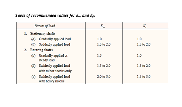
Transcribed Image Text:Table of recommended values for Km and K,
Nature of load
1. Stationary shafts
(a) Gradually applied load
K,
1.0
1.0
(6) Suddenly applied load
1.5 to 2.0
1.5 to 2.0
2. Rotating shafts
(a) Gradually applied or
steady load
(6) Suddenly applied load
with minor shocks only
(c) Suddenly applied load
with heavy shocks
1.5
1.0
1.5 to 2.0
1.5 to 2.0
2.0 to 3.0
1.5 to 3.0
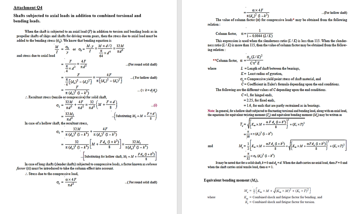
Transcribed Image Text:Attachment Q4
ax 4F
-For hollow shaft)
Shafts subjected to axial loads in addition to combined torsional and
bending loads.
The value of column factor (a) for compressive loads* may be obtained from the following
relation:
1
When the shaft is subjected to an axial load (F) in addition to torsion and bending loads as in
propeller shafts of ships and shafts for driving wom gears, then the stress due to axial load must be
added to the bending stress (0,). We know that bending equation is
Column factor,
a=
F1-0.0044 (L/K)
This expression is used when the slenderness ratio (L/K) is less than 115. When the slender-
ness ratio (L/K) is more than 115, then the value of column factor may be obtained from the follow-
ing relation:
M.y _ M x d/2 32M
or O= 1
%3D
6, (L/K)²
CnE
L = Length of shaft between the bearings,
K= Least radius of gyration,
0, = Compressive yield point stress of shaft material, and
C= Coefficient in Euler's formula depending upon the end conditions.
and stress due to axial load
64
F
4F
%3D
**Column factor, a =
.(For round solid shaft)
xd? nd?
where
F
4F
%3D
.(For hollow shaft)
--
F
.. (* *= djd)
The following are the different values of C depending upon the end conditions.
T (d.)° (1 – k²)
.. Resultant stress (tensile or compressive) for solid shaft,
C=1, for hinged ends,
= 2.25, for fixed ends,
32 м
O, =
Fxd'
32
M +
4F
..()
= 1.6, for ends that are partly restrained as in bearings.
%3D
32M1
Note: In general, for a hollow shaft subjected to fluctuating torsional and bending load, along with an axial load,
the equations for equivalent twisting moment (T) and equivalent bending moment (M) may be written as
stituting M1 = M +
In case of a hollow shaft, the resultant stress,
T.=
a F d, (1+ k)
+ (E, x T)?
K.xM +
32M
4F
T (d, (1 – k*)" * (d,) a – x²)
32
Fd, (1 + k?)
aFd, (l + k*) , K-
M +
aFd, a +k)
1 (d,)' (1 – k*)
a(d,) (1 – x*)
M. =
+ (K, x T)²
and
KxM +
8
Substituting for hollow shaft, Af =M +
It may be noted that for a solid shaft, k=0 and d, =d. When the shaft caies no axial load, then F=0 and
In case of long shafts (slender shafts) subjected to compressive loads, a factor known as column
factor (a) must be introduced to take the column effect into account.
when the shaft carries axial tensile load, then a =1.
.. Stress due to the compressive load,
ax 4F
O =
..(For round solid shaft)
Equivalent bending moment (M.),
M. = K, x M + V(K, × M)² + (K, × T)² |
where
K = Combined shock and fatigue factor for bending, and
K, = Combined shock and fatigue factor for torsion.
Expert Solution
This question has been solved!
Explore an expertly crafted, step-by-step solution for a thorough understanding of key concepts.

This is a popular solution!

Trending now
This is a popular solution!

Step by step
Solved in 6 steps with 6 images

Knowledge Booster


Learn more about
Need a deep-dive on the concept behind this application? Look no further. Learn more about this topic, mechanical-engineering and related others by exploring similar questions and additional content below.Recommended textbooks for you
Mechanics of Materials (MindTap Course List)
Mechanical Engineering
ISBN:
9781337093347
Author:
Barry J. Goodno, James M. Gere
Publisher:
Cengage Learning
Mechanics of Materials (MindTap Course List)
Mechanical Engineering
ISBN:
9781337093347
Author:
Barry J. Goodno, James M. Gere
Publisher:
Cengage Learning