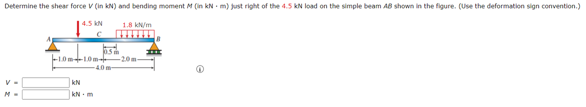
Determine the shear force V (in kN) and bending moment M (in kN • m) just right of the 4.5 kN load on the simple beam AB shown in the figure. (Use the deformation sign convention 4.5 kN 1.8 kN/m 0.5 m +1.0 m--1.0 m- - 2.0 m 4.0 m- V = kN M%3= kN m


Q: H.W 3_ Two aluminum alloy plates (2) are attached to the sides of a wooden beam (1) as shown in…
A:
Q: з KN/m 1,5 KN/m 1,5 KN/m B (m) 1,5 2,6
A:
Q: Draw the shear-force and bending-moment diagrams for a simple beam as shown in Figure Q2 with a…
A:
Q: Q3: Draw the shear force and bending moment diagrams for the loaded beam shown (see figure below). (…
A: Draw the free-body diagram of the beam.
Q: 50 kN/m 20 kN/m Q-1 For the beam loaded as shown in the figure, draw the shear force and bending A…
A: Given: To draw the shear force and bending moment diagram. NOTE: According to Bartleyby's policy we…
Q: q(x) 2. Mesnet
A: For solution refer below images.
Q: The beam subject to loading in the figure; a) Shear force and bending moment diagrams (cut using the…
A: Consider the free body diagram of the beam as shown below. Take the moment about the point B, From…
Q: The cross-sectional dimensions of the beam shown in the figure are a = 4.6 in., b = 5.5 in., d = 4.4…
A:
Q: 1. A rectangular beam120 mm wide by 400 mm deep is loaded as shown in the figure. a) Determine the…
A:
Q: H.W.3 /The simply supported beam in Figure below has a rectangular cross section with dimension (30…
A:
Q: P=80 N q=10 N/m B 100 느=40 m --=40 m 2 2
A: The given beam is shown below – Calculating reaction at support at A and B,
Q: The cantilever beam A B shown in the figure is subjected to a triangular load acting over one-half…
A: On taking moment about A, The force equilibrium in vertical direction, The force equilibrium in…
Q: Consider the beam shown in the figure . Suppose that w1 = 560 N/m , w2 = 280 N/m . Follow the sign…
A: The detiled solution is given below.
Q: The 8 m long cantilever beam shown in the figure below carries a uniformly distributed load of 10…
A:
Q: The simple beam ACB shown in the figure is subjected to a concentrated load P 30 kips and a…
A: Given: Distributed load (q)=3kips/ftConcentrated load (P)=30kips
Q: The beam shown in the figure is supported at roller A and pinned at B and has a uniformly…
A:
Q: 58 kN/m For the beam and loading shown in figure, answer the Hinge questions below -5.5 m- 254 mm 18…
A: Given data: The length of the cantilever having the uniformly distributed load is, L=5.5 m. The…
Q: Abeam with a rectangular cross section is simply supported and loaded at its center with a force P.…
A:
Q: F W 50 mm 20 mm -2 m
A: Free body diagram of the beam:
Q: The cross-sectional dimensions of the beam shown in the figure are a = 4.7 in, b= 6.2 in., d= 4.7…
A:
Q: The maximum bending stress at distance 0.5 m from the built-in right hand end in the structural beam…
A:
Q: The simply supported beam is subjected to the loading and has cross-sectional area as in the figure…
A: Draw a free-body diagram of a given beam. Apply force equilibrium in a vertical direction.…
Q: A wood beam carries the loading shown in the figure. Determine the smallest allowable width b in mm…
A:
Q: Question contains a hinge in the middle. Find the shear force and the bending moment at the Figure 3…
A:
Q: A wood beam carries the loading shown in the figure. calculate the maximum bending stress (in Pa) if…
A: GivenP=4381NW=1747N/ma=1.1mb=2.12mc=1.34mL=95mmh=297mm
Q: H.W.1 /The cantilever beam in Figure below has a rectangular cross section with dimension (20…
A:
Q: Q: Find the value of W which can be applied to the beam shown in figure below. if the maximum…
A: Consider the reaction at the supports RB and the reaction at supports C is Rc. Moment about C,…
Q: The cantilever beam AB shown in the figure is subjected to a uniform load acting throughout one-half…
A: GIVEN DATA A CANITILVER BEAM IS GIVEN
Q: A steel wide-flange beam has the dimensions as shown in the figure below. If it is subjected to…
A: According to the given information we have shear force of v = 86 Kn firstly for the moment of…
Q: The simply supported beam AB is subjected to two concentrated load as shown in figure. Determine:…
A:
Q: A wood beam carries the loading shown in the figure. calculate the magnitude of the bending stress…
A:
Q: A simply supported beam carries a distributed load of 10 kN/m over a span of 5 m and a concentrated…
A: Given Data: udl intensity w=10 KN/m Span L=5 m Point loads =10 KN ,8 KN
Q: Q.2. A beam ABC with an overhang at one end supports a uniform load of intensity 12 kN/m and a…
A:
Q: 150 N Q.4) For the beam and 100 N 100N 160 N/ 160 N/ to e k loading shown in figure, „draw shear…
A:
Q: The beam AB, shown in Figure 1a, with length L = 4.5 m is subjected to a uniform distributed load w…
A:
Q: The beam ABCD with a rectangular cross section carries the loading shown in the figure. Determine…
A: Given question belongs to subject Solid Mechanics and can be solved by determining the maximum…
Q: For the simply supported beam in figure, the shear force at midspan equals: 80 kN 80 kN 2 4 m Select…
A: Given, External force = 80 kN
Q: The overhanging beam ABC in Figure supports a concentrated load and a uniformly distributed load.…
A:
Q: Problem 2 For the beam shown in the figure A) Draw the shear-force and bending-moment diagrams for…
A:
Q: Draw the shear-force and bending-momentdiagrams for beam AB with a sliding support at Aand an…
A: Shear force is the algebraic sum of the vertical forces at any segment of a beam to the right or…
Q: Calculate the shear force V (in kN) and bending moment M (in kN - m) at a cross section located just…
A:
Q: Q1: For the beam ABCD subjected to the loading shown in figure below (B internal hinge) (1) draw the…
A:
Q: For the fixed-ended beam shown in figure below, each end moment equals: P A В L/2- L/2- P/2 O P/8…
A: For the fixed-ended beam shown in figure below, each end moment equals: P/2 P/8 P/16 P/4
Q: Rectangular section and width given in the figure The bending safety stress of the beam with b = 150…
A:
Q: Q4: If the T- cross section of the beam shown in the Figure (3) below has bending stress of 37 MN/m?…
A:
Q: An overhanging beam is subjected to a partial uniform load w 26 kN/m and two pint loads P1 99 kN, P2…
A: Consider the free body diagram: Balancing forces in X direction:RA+RB+99=475+26*9RA+RB=610…
Q: The simple beam AB shown in the figure is subjected to a concentrated load P and a clockwise couple…
A: Shear force is defined as the algebraic sum of all vertical forces acting on a segment from the left…
Q: 1. A simply supported beam with rectangular cross-section is loaded as shown in the figure. Draw the…
A:
Q: 6 kN/m Since the bending safety stress *em = 10 MPa, shear safety stress em = 600 kPa of the…
A: Draw a diagram for the beam. Here, RA and RC are the support reactions as shown in the figure.…

Step by step
Solved in 2 steps with 2 images

- The cross section of a sand wie h beam consisting of aluminum alloy faces and a foam core is shown in the figure. The width b of the beam is 8.0 in, the thickness I of the faces is 0.25 in., and the height hcof the core is 5.5 in. (total height h = 6.0 in). The moduli of elasticity are 10.5 × 10⁶ psi for the aluminum faces and 12.000 psi for the foam core. A bending moment M = 40 kip-in. acts about the z axis. Determine the maximum stresses in the faces and the core using (a) the general theory for composite beams and (b) the approximate theory for sandwich beams.The hollow box beam shown in the figure is subjected to a bending moment M of such magnitude that the flanges yield but the webs remain linearly elastic. (a) Calculate the magnitude of the moment M if the dimensions of the cross section are A = 15 in., A] = 12.75 in., h = 9 in., and ey =7.5 in. Also, the yield stress is eY = 33 ksi. (b) What percent of the moment M is produced by the elastic core?A beam of wide-flange shape, W 8 x 28, has the cross section shown in the figure. The dimensions are b = 6.54 in., h = 8.06 in., fw = 0.285 in., and tf = 0.465 in.. The loads on the beam produce a shear force V = 7.5 kips at the cross section under consideration. Use center line dimensions to calculate the maximum shear stress raiaxin the web of the beam. Use the more exact analysis of Section 5,10 in Chapter 5 to calculate the maximum shear stress in the web of the beam and compare it with the stress obtained in part .
- A W 12 x 50 steel wide-flange beam and a segment of a 4-inch thick concrete slab (see figure) jointly resist a positive bending moment of 95 kip-ft. The beam and slab are joined by shear connectors that are welded to the steel beam. (These connectors resist the horizontal shear at the contact surface.) The moduli of elasticity of the steel and the concrete are in the ratio 12 to 1. Determine the maximum stresses r1 and xtin the steel and concrete, respectively. Note: See Table F-l(a) of Appendix F for the dimensions and properties of the steel beam.Two identical, simply supported beams AB and CD are placed so that they cross each other at their midpoints (sec figure). Before the uniform load is applied, the beams just touch each other at the crossing point. Determine the maximum bending moments (mab)max* and (MCD)max beams AB and CD, respectively, due to the uniform load if the intensity of the load is q = 6.4 kN/m and the length of each beam is L = 4 m.A two-axle carriage that is part of an over head traveling crane in a testing laboratory moves slowly across a simple beam AB (sec figure). The load transmitted to the beam from the front axle is 2200 lb and from the rear axle is 3800 lb. The weight of the beam itself may be disregarded. Determine the minimum required section modulus S for the beam if the allowable bending stress is 17,0 ksi, the length of the beam is 18 ft, and the wheelbase of the carriage is 5 ft. Select the most economical I-beam (S shape) from Table F-2(a), Appendix F.
- A beam supporting a uniform load of intensity q throughout its length rests on pistons at points A, C and B (sec figure). The cylinders are filled with oil and are connected by a tube so that the oil pressure on each piston is the same. The pistons at A and B have diameter d1and the piston at C has diameter D2. (a) Determine the ratio of d2to d1so that the largest bending moment in the beam is as small as possible. Under these optimum conditions, what is the largest bending moment Mmaxin the beam? What is the difference in elevation between point C and the end supports?The cross section of a sandwich beam consisting of fiberglass faces and a lightweight plastic core is shown in the figure. The width b of the beam is 50 mm, the thickness I of the faces is 4 mm, and the height hcof the core is 92 mm (total height A = 100 mm). The moduli of elasticity are 75 GPa for the fiberglass and 1.2 GPa for the plastic. A bending moment M = 275 N · m acts about the z axis. Determine the maximum stresses in the faces and the core using (a) the general theory for composite beams and (b) the approximate theory for sandwich beams.A cantilever beam AB having rectangular cross sections with varying width bxand varying height hxis subjected to a uniform load of intensity q (sec figure). If the width varies linearly with x according to the equation hx= bBxiL^ how should the height hxvary as a function of v in order to have a fully stressed beam? (Express hxin terms of the height hBat the fixed end of the beam.)
- A weight W = 4000 lb falls through a height h = 0.5 in, onto the midpoint of a simple beam of length L = 10 ft (see figure). Assuming that the allowable bending stress in the beam is = 18,000 psi and E = 30 x 10* psi, select the lightest wide-flange beam listed in Table F-l(a) in Appendix F that will be satisfactory.Determine the fixed-end moments (MAand MB) and fixed-end forces (R4and Rs) for a beam of length L supporting a triangular load of maximum intensity q0(see figure). Then draw the shear-force and bending-moment diagrams, labeling all critical ordinates.A hollow steel box beam has the rectangular cross section shown in the figure. Determine the maximum allowable shear force K that may act on the beam if the allowable shear stress is 36 MPa. c