In the following figure(Figure 1), R1 =6.00 , Ra = 6.00 , and R3 =6.00 2. The battery has negligible internal resistance. The current Ia through Rg is 5.00 A Part A What is the current I, through R1? Express your answer with the appropriate units. HA I = Value A Submit Request Answer Figure K 1 of 1 Part B What is the current Iz through R3? R1 Express your answer with the appropriate units. R2 HA ? I3 = Value A R3 Submit Request Answer 近 Part C What is the emnf of the battery? Express your answer with the appropriate units. Value V Submit Request Answer Provide Feedback
In the following figure(Figure 1), R1 =6.00 , Ra = 6.00 , and R3 =6.00 2. The battery has negligible internal resistance. The current Ia through Rg is 5.00 A Part A What is the current I, through R1? Express your answer with the appropriate units. HA I = Value A Submit Request Answer Figure K 1 of 1 Part B What is the current Iz through R3? R1 Express your answer with the appropriate units. R2 HA ? I3 = Value A R3 Submit Request Answer 近 Part C What is the emnf of the battery? Express your answer with the appropriate units. Value V Submit Request Answer Provide Feedback

Chapter27: Service-entrance Equipment
Section: Chapter Questions
Problem 44R

Related questions
Question
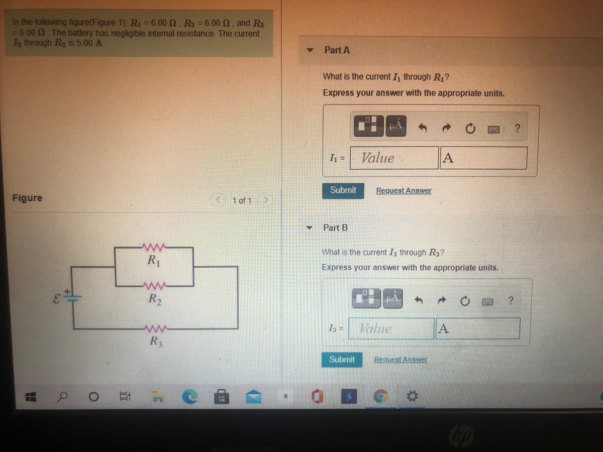
Transcribed Image Text:In the following figure(Figure 1), R1 =6.00 , Ra = 6.00 , and R3
=6.00 2. The battery has negligible internal resistance. The current
Ia through Rg is 5.00 A
Part A
What is the current I, through R1?
Express your answer with the appropriate units.
HA
I =
Value
A
Submit
Request Answer
Figure
K 1 of 1
Part B
What is the current Iz through R3?
R1
Express your answer with the appropriate units.
R2
HA
?
I3 =
Value
A
R3
Submit
Request Answer
近
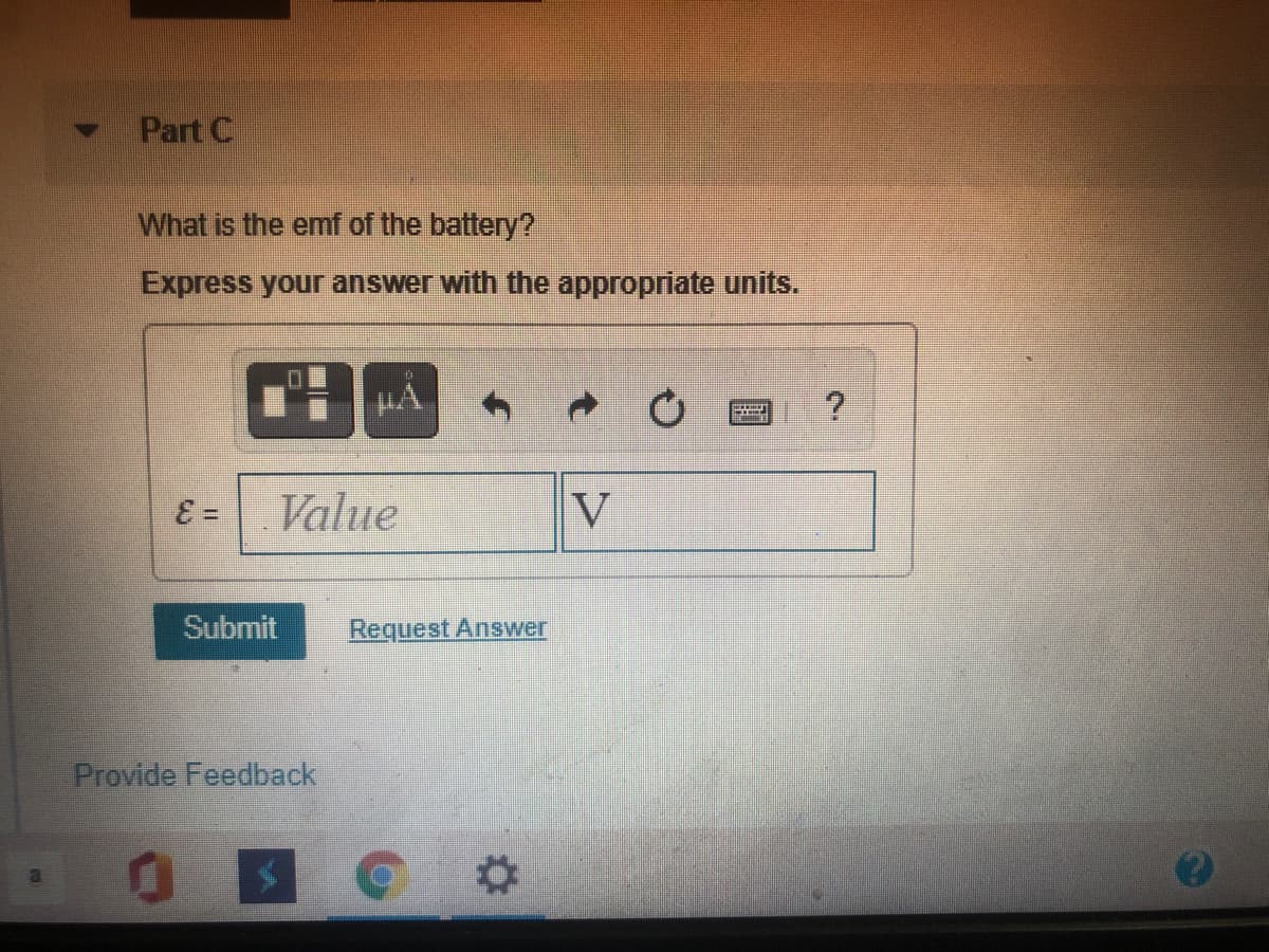
Transcribed Image Text:Part C
What is the emnf of the battery?
Express your answer with the appropriate units.
Value
V
Submit
Request Answer
Provide Feedback
Expert Solution
This question has been solved!
Explore an expertly crafted, step-by-step solution for a thorough understanding of key concepts.

This is a popular solution!

Trending now
This is a popular solution!

Step by step
Solved in 2 steps with 2 images

Recommended textbooks for you
EBK ELECTRICAL WIRING RESIDENTIAL
Electrical Engineering
ISBN:
9781337516549
Author:
Simmons
Publisher:
CENGAGE LEARNING - CONSIGNMENT
EBK ELECTRICAL WIRING RESIDENTIAL
Electrical Engineering
ISBN:
9781337516549
Author:
Simmons
Publisher:
CENGAGE LEARNING - CONSIGNMENT