Find the moment about A and C for the loaded section as shown in figure. The forces F1 =20 N, F2 = 20 N, F3 = 32N, F4 =36 N, AB =14 m, BC=10 m, CD = 11 m, 0,=45°. %3D
Find the moment about A and C for the loaded section as shown in figure. The forces F1 =20 N, F2 = 20 N, F3 = 32N, F4 =36 N, AB =14 m, BC=10 m, CD = 11 m, 0,=45°. %3D

Mechanics of Materials (MindTap Course List)
9th Edition
ISBN:9781337093347
Author:Barry J. Goodno, James M. Gere
Publisher:Barry J. Goodno, James M. Gere
Chapter4: Shear Forces And Bending Moments
Section: Chapter Questions
Problem 4.5.33P: The shear-force diagram for a beam is shown in the figure. Assuming that no couples act as loads on...

Related questions
Question
Solve it quickly please
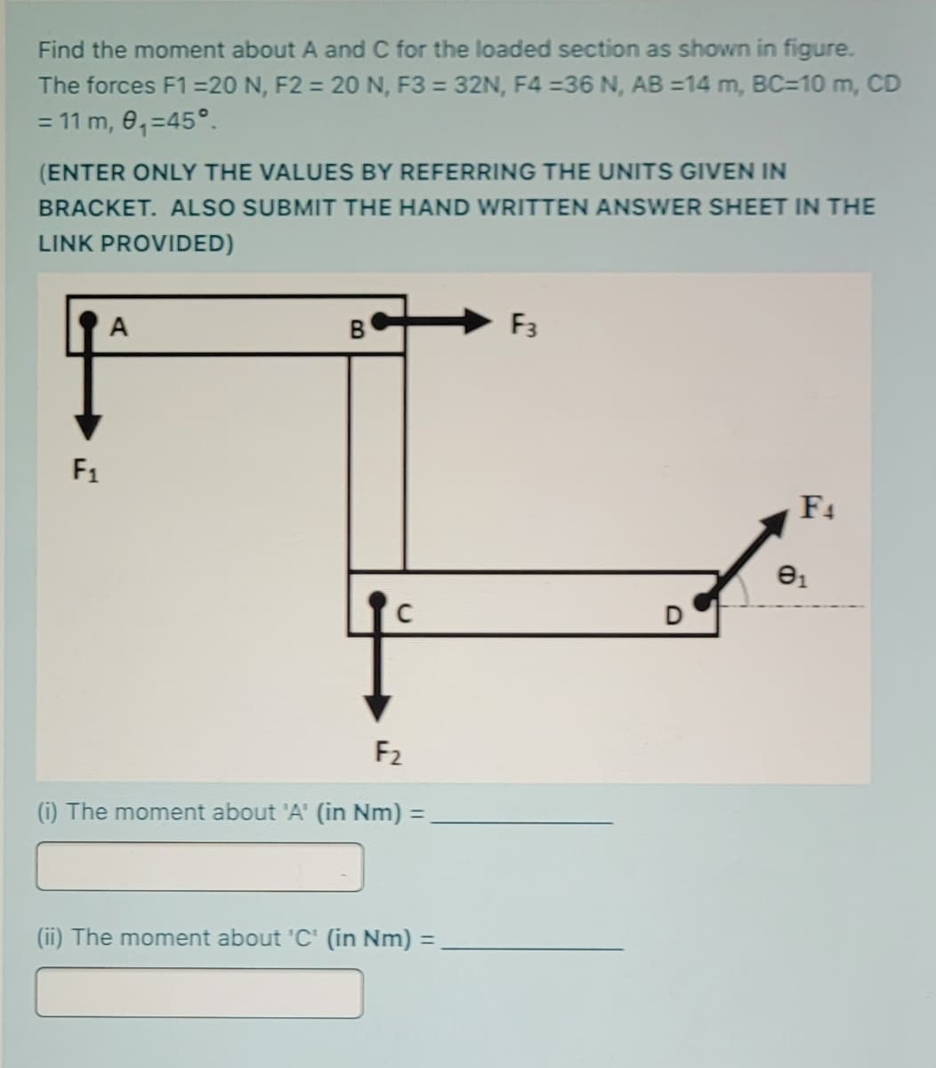
Transcribed Image Text:Find the moment about A and C for the loaded section as shown in figure.
The forces F1 =20 N, F2 = 20 N, F3 = 32N, F4 =36 N, AB =14 m, BC=10 m, CD
= 11 m, 0,=45°.
(ENTER ONLY THE VALUES BY REFERRING THE UNITS GIVEN IN
BRACKET. ALSO SUBMIT THE HAND WRITTEN ANSWER SHEET IN THE
LINK PROVIDED)
A
F3
F1
F4
F2
(i) The moment about 'A' (in Nm) =
%3D
(ii) The moment about 'C' (in Nm) =
Expert Solution
This question has been solved!
Explore an expertly crafted, step-by-step solution for a thorough understanding of key concepts.

Step by step
Solved in 2 steps with 1 images

Knowledge Booster


Learn more about
Need a deep-dive on the concept behind this application? Look no further. Learn more about this topic, mechanical-engineering and related others by exploring similar questions and additional content below.Recommended textbooks for you
Mechanics of Materials (MindTap Course List)
Mechanical Engineering
ISBN:
9781337093347
Author:
Barry J. Goodno, James M. Gere
Publisher:
Cengage Learning
Mechanics of Materials (MindTap Course List)
Mechanical Engineering
ISBN:
9781337093347
Author:
Barry J. Goodno, James M. Gere
Publisher:
Cengage Learning