
Introductory Circuit Analysis (13th Edition)
13th Edition
ISBN: 9780133923605
Author: Robert L. Boylestad
Publisher: PEARSON
expand_more
expand_more
format_list_bulleted
Related questions
Question
thumb_up100%
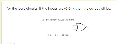

Transcribed Image Text:for the logic circuits, if the inputs are (0,0,1), then the output will be:
15. given output (0,0, 1) output are
A) 0
B)1
C) None

Transcribed Image Text:which of the following inputs give a high (1) output of EX- OR gate
Expert Solution
This question has been solved!
Explore an expertly crafted, step-by-step solution for a thorough understanding of key concepts.

Step by stepSolved in 2 steps

Knowledge Booster


Learn more about
Need a deep-dive on the concept behind this application? Look no further. Learn more about this topic, electrical-engineering and related others by exploring similar questions and additional content below.Similar questions
- Q3 Find the sequence of the counter in the figure below. Begin with the counter cleared. D 00.0 Qo K K Q K CLR CLR CLR CK Note: Determine the logic expressions for the inputs Jo, Ko, J1, K1, J2 and K2 firstlyarrow_forwardI need the answer as soon as possiblearrow_forwardDesign a 5 bits input logic circuit that can be output F to go active (High) under the following conditions: - All inputs are logic 1" - An odd number of inputs are logic 1" - Non of the inputs are logic 1"arrow_forward
- 1. Consider the following two logic circuits. VDD A-6 B-d6 A-6 B-6 -6 -6 F VDD F t t A Circuit A Circuit B a. Do these two circuits implement the same logic function? If yes, what is that logic function? If no, give Boolean expressions for both circuits. b. Will these two circuits' output resistances always be equal to each other? c. Will these two circuits' rise and fall times always be equal to each other? Why or why not?arrow_forwardSuppose r0=0x300010A0, r2 = 0x00000011, and the memory layout is as follows. Address Data 0x300010A7 0x72 0x300010A6 0xA5 0x300010A5 0x9F 0x300010A4 0x00 0x300010A3 0x50 0x300010A2 0x2B 0x300010A1 0xA5 0x300010A0 0x01 What is the value of 10 and r1 after executing LDR r1, [r0, #2]?arrow_forward1. Design a combinational logic circuit with three inputs A, B and C and one output X. When only one input is 1, output is 1. When none of input is 1, output is also 1. Otherwise, output is 0.arrow_forward
arrow_back_ios
arrow_forward_ios
Recommended textbooks for you
- Introductory Circuit Analysis (13th Edition)Electrical EngineeringISBN:9780133923605Author:Robert L. BoylestadPublisher:PEARSON
 Delmar's Standard Textbook Of ElectricityElectrical EngineeringISBN:9781337900348Author:Stephen L. HermanPublisher:Cengage Learning
 Programmable Logic ControllersElectrical EngineeringISBN:9780073373843Author:Frank D. PetruzellaPublisher:McGraw-Hill Education
  Fundamentals of Electric CircuitsElectrical EngineeringISBN:9780078028229Author:Charles K Alexander, Matthew SadikuPublisher:McGraw-Hill Education
 Electric Circuits. (11th Edition)Electrical EngineeringISBN:9780134746968Author:James W. Nilsson, Susan RiedelPublisher:PEARSON
 Engineering ElectromagneticsElectrical EngineeringISBN:9780078028151Author:Hayt, William H. (william Hart), Jr, BUCK, John A.Publisher:Mcgraw-hill Education,
Introductory Circuit Analysis (13th Edition)
Electrical Engineering
ISBN:9780133923605
Author:Robert L. Boylestad
Publisher:PEARSON
Delmar's Standard Textbook Of Electricity
Electrical Engineering
ISBN:9781337900348
Author:Stephen L. Herman
Publisher:Cengage Learning
Programmable Logic Controllers
Electrical Engineering
ISBN:9780073373843
Author:Frank D. Petruzella
Publisher:McGraw-Hill Education
Fundamentals of Electric Circuits
Electrical Engineering
ISBN:9780078028229
Author:Charles K Alexander, Matthew Sadiku
Publisher:McGraw-Hill Education
Electric Circuits. (11th Edition)
Electrical Engineering
ISBN:9780134746968
Author:James W. Nilsson, Susan Riedel
Publisher:PEARSON
Engineering Electromagnetics
Electrical Engineering
ISBN:9780078028151
Author:Hayt, William H. (william Hart), Jr, BUCK, John A.
Publisher:Mcgraw-hill Education,