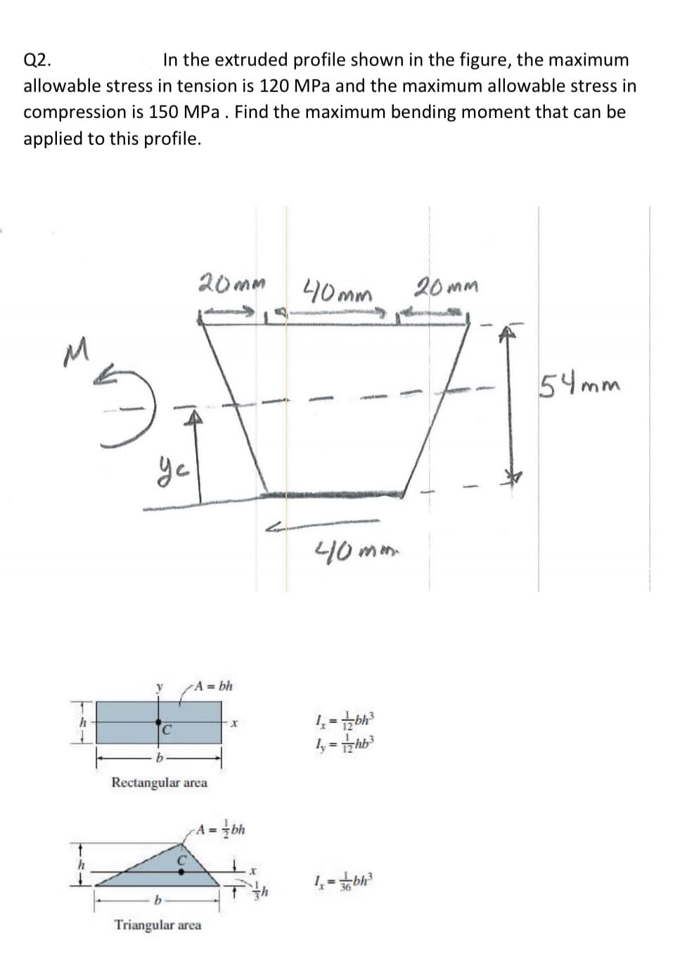
Q2. In the extruded profile shown in the figure, the maximum allowable stress in tension is 120 MPa and the maximum allowable stress in compression is 150 MPa . Find the maximum bending moment that can be applied to this profile. 20mm 40mm 20 mm 54mm ye 40mmm
Q: * Given: Maximum shear FORCE=13 KN, and moment of inertia = 120 x 10^6 mm^4. Find the maximum shear…
A:
Q: A solid shaft is subjected to two shear forces and a torque as shown in the figure. Assume that the…
A: Given data:- L=205 mm Vy= 9kN Vz =19kN T= 499 N-m d =61 mm
Q: Q4) The figure below shows the shear force diagram of a beam with their cross-section. a) Find the…
A: As you have posted a multiple question, we are supposed to answer the first 3 subparts of the first…
Q: A wood beam carries the loading shown in the figure calculate the magnitude of the bending stress…
A:
Q: Question 1 A plastic-lined steel pipe has the cross-sectional shape shown in Figure Q1 The steel…
A: a)Elasticity of steel is equal to seven times of elasticity of plastic.
Q: The screw of the clamp exerts a compressive force of 500 N on the wooden blocks. The cross section…
A: Given: The compressive force on wooden block, P = 500 N The cross-section of clamp at a-a, A = 3 cm…
Q: Q1 For the beam shown in figure below, draw the shearing force and bending moment diagrams showing…
A:
Q: Values for the figure are given in the following table. Note the figure may not be to scale.…
A:
Q: Q1) A simply supported beam having a length of 7 meters carries a uniformly distributed load of…
A: Any action that can change the state of motion is called force, Force is described by its magnitude,…
Q: Q: Find the value of W which can be applied to the beam shown in figure below. if the maximum…
A:
Q: Since the bending safety stress em = 10 MPa, shear safety stress em = 600 kPa of the rectangular…
A:
Q: Question 2) arm of Figure B from point x z plane, a horizontal angle of θ = 38 ° angled F = 29…
A:
Q: Derive the following formula for the distancee from the centerline of the wall to the shearcenter S…
A:
Q: The screw of the clamp exerts a compressive force of 500 N on the wooden blocks. The cross section…
A:
Q: Q2/ A beam has a cross section as shown below with unknown dimensions of the flange (b₂) and the web…
A: To find: The unknown dimension of the flange b2 and the web b1. Given: The tensile stress at point A…
Q: 250 N 200 N A 2 m 2 m 500 N The bended pipe shown in the figure has a hollow circular cross section…
A: Write the given data with suitable variables.
Q: Ex: A Torque (T) is applied to a solid taper shaft with built-in ends, as shown in Figure ,…
A: Write the torque developed on the taper shaft. T=20 kN·m=20 kN·m×1000 N·m1 kN·m=20×103 N·m Write…
Q: P3 (kN) P4 (kN) B 30 kN A L3 (m) L4 (m)
A: Solution: Reactions and B and C can be found using static equilibrium conditions, therefore,…
Q: The maximum bending stress at distance 0.5 m from the built-in right hand end in the structural beam…
A:
Q: axial force, shear force and bending moment at a section
A: EXPLANATION-
Q: 4.3 (A). A conveyor beam has the cross-section shown in Fig. 4.24 and it is subjected to a bending…
A: A1=25*150A2=200*100A3=100*50y¯=A1y1+A2y2+A3y3A1+A2+A3y1=50+100+1502 =225 mmy2=50+1002=100 mmy3=25…
Q: For the system shown in the figure, find the maximum internal shear force in kN. Hint: you will need…
A:
Q: Question contains a hinge in the middle. Find the shear force and the bending moment at the Figure 3…
A:
Q: Q: Find the value of W which can be applied to the beam shown in figure below. if the maximum…
A: Consider the reaction at the supports RB and the reaction at supports C is Rc. Moment about C,…
Q: A steel wide-flange beam has the dimensions as shown in the figure below. If it is subjected to…
A: According to the given information we have shear force of v = 86 Kn firstly for the moment of…
Q: In the figure, both ends of the rectangular plate are under the effect of a force p = 150kN. What is…
A:
Q: 40 N.m Da 0.5 m 280 N.m 150 N.m 2 0.3 m 0.4 m
A:
Q: Q.2. A beam ABC with an overhang at one end supports a uniform load of intensity 12 kN/m and a…
A:
Q: Q2) A rectangular beam 120mm wide by 400mm deep is loaded as shown in the figure. Find "P" to cause…
A: Any action that can change the state of motion is force. Force is described by its magnitude, point…
Q: (1) (2) |(3) a (4) (5) В с b A, = mm? 159 A2 = A3 = 33 mm? A4 = As = 46 mm? 26.5 mm Y, = Y2 = y3 =…
A:
Q: arm of Figure B from point x z plane, a horizontal angle of θ = 38 ° angled F = 29 kN force sized…
A: Given data, The angle θ=38° Applied Force, F = 29000 N Applied moment, M = 17000 N-m Length of arm…
Q: A solid circular torsional member OPQ is subjected to torsional moments as shown in the figure (not…
A: GIVEN DATA- A STEPPED SHAFT GIVEN WE HAVE TO FIND MAXIMUM SHEAR STRESS IN SHAFT
Q: For the simply supported beam in figure, the shear force at midspan equals: 80 kN 80 kN 2 4 m Select…
A: Given, External force = 80 kN
Q: Forces of magnitude F; =7 kN in the +y direction and F 2 =13 kN in Question 2) the -z direction are…
A:
Q: in the figure. (a) Determine the shear force V and bending moment M at a cross section located 18 ft…
A:
Q: If all the shafts are in the opposite shape of the shear modulus Equal to 101 GPa A) Find the…
A: Given data: G=101 GPa Need to determine the maximum amount of shear stress and angle of twist at…
Q: Q/ The figure shows the vertical cross- section of a beam which at this section is subjected to a…
A: Answer: (a) The Bending stresses: ◆ Tensile stress : 1 MPa ◆ Compressive stress : 0.6 MPa (b) The…
Q: Beam cross section is shown in Figure Q3 and given the second moment of area is I= 20.85 x 106 mm*.…
A: Find the shear stress at point M, N, O, P and draw stress distribution over the cross section
Q: and moment at an arbitrary poistion x of AB segment, in terms of P and x, be careful of the sign.…
A: given:l1l=0.65P=mg
Q: 1. Find the external reactions, the axial force ,shear force and bending moment at the crown C. 30…
A: To find external support reactions and internal forces at point C
Q: Q4: If the T- cross section of the beam shown in the Figure (3) below has bending stress of 37 MN/m?…
A:
Q: Q2 The internal bending moment in a beam with a cross sectional area shown in the figure is 500 a in…
A: Given, M= 500 N-m, Now A1=(50+25+50)×25=3125 mm2and area A2=100×35= 3500 mm2 CG of area A1, x1=0,…
Q: For the beam shown in figure below, draw the shearing force and bending moment diagrams showing the…
A:
Q: Determine the maximum and minimum value of the normal stress caused by the bending moment M,-20NM on…
A:
Q: Consider the two-member frame shown. Suppose that w1 = 280 N/m , w2 = 450 N/m . Follow the sign…
A:
Q: For the figure shown below. Find the maximum allowable value of P if the bending stresses are not…
A:
Q: The bending moment acting on the triangular cross section of a beam is M = 36 kN.m (concave upward).…
A: Data given -
Q: Box beam in the figure is made of four pieces of wood nailed to each other as shown. has been made.…
A: Given that, Maximum allowable vertical shear in the beam, F=180a=18,b=16,c=2a=36,d=5b=80, Maximum…
Q: If the cross section shown in the figure has a shear stress of 300 Psi at point P (located 0.25 in…
A: Given data:- Shear stress at point P(below 0.25 in from top fiber) is 300 psi. Find the shear force…
Trending now
This is a popular solution!
Step by step
Solved in 2 steps with 2 images
- Consider the preceding problem if the beam has width h = 15 mm, the aluminum strips have thickness t = 3 mm, the plastic segments have heights d = 40 mm and 3 tf = 120 mm, and the total height of the beam is h = 212 mm. Also, the moduli of elasticity are EA= 75 GPa and Ep=3 GPa, respectively. Determine the maximum stresses o., and o\, in the aluminum and plastic, respectively, due to a bending moment of 1.0 kN - m.A thin-walled rectangular tube has uniform thickness t and dimensions a x b to the median line of the cross section (see figure). How does the shear stress in the tube vary with the ratio = a/b if the total length Lmof the median line of the cross section and the torque T remain constant? From your results, show that the shear stress is smallest when the tube is square (ß = 1).A circular aluminum tube subjected to pure torsion by torques T(sec figure) has an outer radius r2equal to 1.5 times the inner radius r1. (a) If the maximum shear strain in the tube is measured as 400 × 10-6 rad, what is the shear strain y1at the inner surface? (b) If the maximum a1lo-abk rate of twist is 0.125 °/m and the maximum shear strain is to be kept at 400 × 10-6 rad by adjusting the torque T, that is the minimum required outer radius ( r2)Min?
- The beam ABC shown in the figure is simply supported at A and B and has an overhang from B to C. The loads consist of a horizontal force P1= 4,0 kN acting at the end of a vertical arm and a vertical force P2= 8.0 kN acting at the end of the overhang, Determine the shear force Fand bending moment M at a cross section located 3,0 m from the left-hand support. Note: Disregard the widths of the beam and vertical arm and use centerline dimensions when making calculations, Find the value of load A that results in V = 0 at a cross section located 2.0 m from the left-hand support. If P2= 8.0 kN, find the value of load P1that results in M = 0 at a cross section located 2,0 m from the left-hand support.A wood beam reinforced by an aluminum channel section is shown in the figure. The beam has a cross section of dimensions 150 mm x 250 mm, and the channel has a uniform thickness of 6.5 mm. If the allowable stresses in the wood and aluminum are 8 M Pa and 38 M Pa, respectively, and if their moduli of elasticity are in the ratio 1 to 6, what is the maximum allowable bending moment for the beam?A thin-walled steel tube of rectangular cross section (see figure) has centerline dimensions b = 150 mm and h = 100 mm. The wall thickness t is constant and equal to 6.0 mm. Determine the shear stress in the tube due to a torque T = 1650 N · m. Determine the angle of twist (in degrees) if the length L of the tube is 1.2 m and the shear modulus G is 75 GPa.
- Solve the preceding problem if the length L = 56 in., the inner radius r1— 1.25 in., the angle of twist is 0.5°, and the allowable shear strain is 0.0004 rad.At a full d raw, an archer applies a pull of 130 N to the bowstring of the bow shown in the figure. Determine the bending moment at the midpoint of the bow.The cross section of a composite beam made of aluminum and steel is shown in the figure. The moduli of elasticity are TA= 75 GPa and Es= 200 GPa. Under the action of a bending moment that produces a maximum stress of 50 M Pa in the aluminum, what is the maximum stress xs in the steel? If the height of the beam remains at 120 mm and allowable stresses in steel and aluminum are defined as 94 M Pa and 40 M Pa, respectively, what heights h and h. arc required for aluminum and steel, respectively, so that both steel and aluminum reach their allowable stress values under the maximum moment?
- A long, thin-walled tapered tube AB with a circular cross section (see figure) is subjected to a torque T. The tube has length L and constant wall thickness t. The diameter to the median lines of the cross sections at the ends A and B are dAand dB, respectively. Derive the following formula for the angle of twist of the tube: Hint: If the angle of taper is small, you may obtain approximate results by applying the formulas for a thin-walled prismatic tube to a differential element of the tapered tube and then integrating along the axis of the tube.Consider the beam with an overhang shown in the figure. Determine the shear force V and bending moment M at a cross section located 18 ft from the left-hand end A. Find the required magnitude of load intensity q acting on the right half of member SC that will result in a zero shear force on the cross section IS ft from A..17 A mountain-bike rider going uphill applies torque T = Fd(F = l5lb, d = 4 in.) to the end of the handlebars ABCD by pulling on the handlebar extenders DE. Consider the right half of the handlebar assembly only (assume the bars are fixed at the fork at A). Segments AB and CD are prismatic with lengths L, = 2 in.andL3 = 8.5 in, and with outer diameters and thicknesses d01 = 1.25 in. 101 = 0.125 in. and d03 = O.87in.,i03 = 0.ll5in, respectively as shown. Segment BC’ of length L, = 1.2 in. however. is tapered, and outer diameter and thickness vary linearly between dimensions at B and C. Consider torsion effects only. Assume G = 4000 ksi is constant. Derive an integral expression for the angle of twist of half of the handlebar tube when it is subjected to torque T = Fd acting at the end. Evaluate ‘b1-, for the given numerical1ues.