
Database System Concepts
7th Edition
ISBN: 9780078022159
Author: Abraham Silberschatz Professor, Henry F. Korth, S. Sudarshan
Publisher: McGraw-Hill Education
expand_more
expand_more
format_list_bulleted
Related questions
Question
Please help me with this. I am having trouble understanding how to make this half adder circuit on TinkerCAD and how the truth table looks
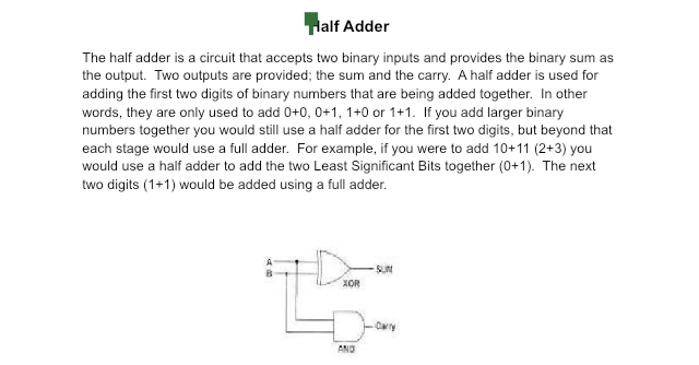

Transcribed Image Text:Half Adder
The half adder is a circuit that accepts two binary inputs and provides the binary sum as
the output. Two outputs are provided; the sum and the carry. A half adder is used for
adding the first two digits of binary numbers that are being added together. In other
words, they are only used to add 0+0, 0+1, 1+0 or 1+1. If you add larger binary
numbers together you would still use a half adder for the first two digits, but beyond that
each stage would use a full adder. For example, if you were to add 10+11 (2+3) you
would use a half adder to add the two Least Significant Bits together (0+1). The next
two digits (1+1) would be added using a full adder.
XOR
AND
-SUN
Cary
Expert Solution
This question has been solved!
Explore an expertly crafted, step-by-step solution for a thorough understanding of key concepts.

This is a popular solution

Trending nowThis is a popular solution!

Step by stepSolved in 3 steps

Knowledge Booster


Learn more about
Need a deep-dive on the concept behind this application? Look no further. Learn more about this topic, computer-science and related others by exploring similar questions and additional content below.Similar questions
- Build the bistable 555 circuit on TinkerCAD, where the output is an LED.arrow_forwardNote: I just need to know the correct answer. Thank you from now. This question's answer is very important for me.arrow_forwardWhat is the distinction between Mealy state machines and Moore state machines?arrow_forward
- Create the half adder out of logic gates.Demonstrate the addition of the following bits (inputs) and their result on the adder you built.x = 1, y = 1x = 0, y = 0x = 1, y = 0arrow_forwardCan you develop a digital circuit based off the given example circuit I have?arrow_forwardbuild a full adder circuit with I/O switched on input wires, LEDs on output and naming input and output wires properlyarrow_forward
arrow_back_ios
arrow_forward_ios
Recommended textbooks for you
- Database System ConceptsComputer ScienceISBN:9780078022159Author:Abraham Silberschatz Professor, Henry F. Korth, S. SudarshanPublisher:McGraw-Hill Education
 Starting Out with Python (4th Edition)Computer ScienceISBN:9780134444321Author:Tony GaddisPublisher:PEARSON
 Digital Fundamentals (11th Edition)Computer ScienceISBN:9780132737968Author:Thomas L. FloydPublisher:PEARSON
  C How to Program (8th Edition)Computer ScienceISBN:9780133976892Author:Paul J. Deitel, Harvey DeitelPublisher:PEARSON
 Database Systems: Design, Implementation, & Manag...Computer ScienceISBN:9781337627900Author:Carlos Coronel, Steven MorrisPublisher:Cengage Learning
 Programmable Logic ControllersComputer ScienceISBN:9780073373843Author:Frank D. PetruzellaPublisher:McGraw-Hill Education
Database System Concepts
Computer Science
ISBN:9780078022159
Author:Abraham Silberschatz Professor, Henry F. Korth, S. Sudarshan
Publisher:McGraw-Hill Education
Starting Out with Python (4th Edition)
Computer Science
ISBN:9780134444321
Author:Tony Gaddis
Publisher:PEARSON
Digital Fundamentals (11th Edition)
Computer Science
ISBN:9780132737968
Author:Thomas L. Floyd
Publisher:PEARSON
C How to Program (8th Edition)
Computer Science
ISBN:9780133976892
Author:Paul J. Deitel, Harvey Deitel
Publisher:PEARSON
Database Systems: Design, Implementation, & Manag...
Computer Science
ISBN:9781337627900
Author:Carlos Coronel, Steven Morris
Publisher:Cengage Learning
Programmable Logic Controllers
Computer Science
ISBN:9780073373843
Author:Frank D. Petruzella
Publisher:McGraw-Hill Education