M1 B A |1.5 m - 2 m -2 m P1 1.5 m 
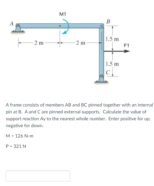
A frame consists of members AB and BC pinned together with an internal pin at B. A and C are pinned external supports. Calculate the value of support reaction Ay to the nearest whole number. Enter positive for up, negative for down. M = 126 N-m P = 321 N
Q: 10) The 40-mm-diameter A-36 steel rod is subjected to the axial forces shown. Take E = 200 Pa.…
A:
Q: The frame for a sign is fabricated from a thin, flat steel bar stock of mass per unit length 4.73…
A:
Q: The truss is subjected to the system of forces as shown in the following figure. The truss is…
A:
Q: Q 2: The homogeneous wire ADOBC is bent into a semicircular arc and two straight section as shown.…
A: The single load acting on the point A is given as,F=20 N The force couple is acting on the point B…
Q: (b) The steel shaft has a diameter of 40 mm and is fixed at its ends A and B as shown in Figure…
A: For solution refer below images.
Q: All the tension/compression members of the frame structure shown in the figure are pin-jointed and…
A:
Q: Number 1
A: Solution: The reaction at A and B is calculated for the given beam as : The total load on the beam…
Q: M D B- L+- +- 1.5L 1.5L-1.5L - 0.5L 0.5L A frame consists of two members, AD and DBC that are…
A: Draw the free body diagram for the above problem.
Q: A steel rod is acted upon by the loading shown below. 50 mm2 is the area of the circular rod. The…
A: Given data: The cross-sectional area of steel rod, A = 50 mm2. Modulus of elasticity for steel, E =…
Q: Determine the internal resultants FG, VG, and MG on the cross section at G of the horizontal frame…
A:
Q: The system with two pin supports, and having an internal pin at C, is subject to two horizontal…
A:
Q: I. A steel rod is acted upon by the loading shown below. 50 mm² is the area of the circular rod. The…
A: Given data Area of cross-section (A) = 50 mm2 Est = 200 GPa To determine a) Force in segment AB,…
Q: The elements of a floor jack are shown in the figure. The figure CDFE is a parallelogram. Calculate…
A: ∑Md=0 1.25EFcosα + 1.25EFsinα = 0 EF=0 BY equating the sum of forces in x-direction and y-direction…
Q: The assembly consists of two rods AC and BD attached to the 100-lb uniform rigid beam AB. There is a…
A:
Q: Solve the following problems completely. Include the FBD with proper labels. 1. The truss is…
A:
Q: Compute for the vertical reaction at the hinged support at C. Given the following data and figure:…
A: P1=9 NP2=17 NF1=12 Nx=2 mz=5 my=7 m
Q: 30 cm 40 cm - 70 15 cm | 250 kg 35 cm 30 cm A 250 kg load is supported by a frame as shown in the…
A: A pin support will exert both horizontal and vertical components of reaction. The support A is pin…
Q: The rods 1, 2, and 3 shown below are welded together, mounted between two rigid walls and subjected…
A: Given data as per question Length of rod 1 and 3 =1 m Length of rod 2 =1.8 m…
Q: Construct the reduced stiffness matrix of the shown truss, Fig. 3.Then determine the nodal…
A: L1=L2=2mL2=252mA1=A2=A3=80mm2E=200GpaE=200×103N/mm2
Q: 9. The rigid bars ABC and CD are supported by pins at A and D and by a steel rod at B. There is a…
A: First we need to calculate load on the string.
Q: The machine element given in the figure is subject to variable load. a) Draw the moment diagrams. b)…
A:
Q: SAMPLE PROBLEM 2: Assume that AE are equal for each rod Reqd: Internal forces for member AB, CD, EF…
A: Given Data: Length of the beam, L=0.8 m
Q: 9. The rigid bars ABC and CD are supported by pins at A and D and by a steel rod at B. There is a…
A: GIVEN DATA- A RIGID BAR ABC AND CD GIVEN SUPPORTED BY STEEL ROD WE HAVE TO FIND DISPLACEMENT AT…
Q: For the figure shown, determine the horizontal and vertical components, respectively, of the hinge…
A:
Q: Problem 1. P 3 m D 3 m B E 3 m A F -7m-| For the frame shown with P = 87 N, determine the forces at…
A:
Q: The rigid bars AB and CD shown in Figure below are supported by pins at A and C and the two rods.…
A: For the aluminum cable, Length of the Aluminum, LAl=2m=2000 mm Area of the aluminum, AAl=500mm2…
Q: Question 3: Given properties of the system are q1=15 kN/m, q=20KN/m, hj=30m, Lı=30m and L=15m. If…
A:
Q: Q3/Determine the vertical movement of point (B) for the rigid bar (AB) which is supported by two…
A: Given: The area of bronze rod, ABr = 400 mm2 The length of bronze rod, LBr = 2.5 m The modulus of…
Q: Q 2 : The homogeneous wire ADOBC is bent into a semicircular arc and two straight section as shown.…
A:
Q: Q1: A: Draw a Free Body Diagram of the bars AD and BC shown in the figure. Assume all hinges to be…
A: Solution:
Q: 4) Use the method of members to find the true magnitude and direction of the forces in the members…
A:
Q: 1. A homogeneous 800 kg bar AB is supported at either end by 9 cable. Calculate the sma llest area…
A:
Q: Q.6 Determine the force in members ac,be,ce,ei & gh of truss shown in figure 3m + 3m 4m h 11 g + 4m…
A: GIVEN DATA - A PLANE TRUSS GIVEM WE HAVE TO FIND FORCES IN GIVEN MEMBER CONCEPT USED-METHOD OF JOINT
Q: Specily where th (c) Find the support reactions at A and C (As shown in the figure, A is a pin…
A:
Q: 1. Use the method of sections to determine the forces in members BD, CD, and CE of the Warren truss…
A:
Q: Mechanics of deformable bodies
A:
Q: The figure shows a setup where when the member AB is horizontal and the unstretched aluminum bar…
A:
Q: 10. The rigid bars shown are separated by a roller and hinged at A and D. Bar AC is supported by a…
A:
Q: Find reaction at C for a frame shown. using Consistent Deformations Method and Least Work Method 6 m…
A: Total Strain energy for the frame,U=Strain energy in semicircular portion+Strain energy in straight…
Q: 2 ft -2 ft 90. 65 200 lb 100 lb 2. A beam AB is loaded as shown. The beam is pin-connected to the…
A: According to the given details in the question. We need to find reaction at A and tension in the…
Q: Compute for the horizontal pin support at D. (A) 10.5 N B) 11.21 N C) 12.5 N D) 15.4 N 2.08 N A 4.15…
A:
Q: ermine Ra at hinge and RB at roller supPport. 10 KN 100 KN 60° W÷10 KN/m 20Kn/m A 6 m 4m 2m
A: To find the reaction supports at A and B The hinge support is replaced by two reaction forces RAx…
Q: The pin at O can support a maximum force of 3.5 kN. What is the corresponding maximum load L which…
A: For the given mechanical system Max. support Reaction at O = 3.5 kN Let the support reaction…
Q: -1.5 m 10 kN- 1 m E 1 m D. 3D 1 m A B
A:
Q: A mechanism carries a constant load P applied to the seat as shown. For the angle 8, determine the…
A:
Q: The structure in the sketch below consists of the two members ABC and CDE which are pin- connected…
A:
Q: Situation - The walkway ABC of the footbridge is stiffened by adding the cable ADC and the short…
A: Find the required values Given data:- Length = 5 m h = 0.9 m Diameter of cable = 8 mm
Q: For the figure shown, determine the horizontal and vertical components, respectively, of the hinge…
A:
Q: The assembly consists of two rods AC and BD attached to the 100-lb uniform rigid beam AB. There is a…
A:
Q: 2.0 m L2 1.0 m A beam is supported by a pin connection at B and a roller support at D. An upwards…
A:
Trending now
This is a popular solution!
Step by step
Solved in 2 steps with 1 images
- A long re Lai nine: wall is braced by wood shores set at an angle of 30° and supported by concrete thrust blocks, as shown in the first part of the figure. The shores are evenly spaced at 3 m apart. For analysis purposes, the wall and shores are idealized as shown in the second part of the figure. Note that the base of the wall and both ends of the shores are assumed to be pinned. The pressure of the soil against the wall is assumed to be triangularly distributed, and the resultant force acting on a 3-meter length of the walls is F = 190 kN. If each shore has a 150 mm X 150 mm square cross section, what is the compressive stressA sign for an automobile service station is supported by two aluminum poles of hollow circular cross section, as shown in the figure. The poles are being designed to resist a wind pressure of 75 lb/ft" against the full area of the sign. The dimensions of the poles and sign are hx= 20 ft, /r =5 ft, and h = 10 ft. To prevent buckling of the walls of the poles, the thickness e is specified as one-tenth the outside diameter d. (a) Determine the minimum required diameter of the poles based upon an allowable bending stress of 7500 psi in the aluminum. (b) Determine the minimum required diameter based upon an allowable shear stress of 300 psi.An elevated jogging track is supported at intervals by a wood beam AB (L = 7.5 ft) that is pinned at A and supported by steel rod BC and a steel washer at B. Both the rod (dBC= 3/16 in.) and the washer (dB= 1.0 in.) were designed using a rod tension force of TBC=415 lb. The rod was sized using a factor of safely of 3 against reaching the ultimate stress tru— 60 ksi. An allowable bearing stress sba= 565 psi was used to size the washer at B. A small platform HF is suspended below a section of the elevated track to support some mechanical and electrical equipment. The equipment load is uniform load q = 50 lb/ft and concentrated load WE= 175 lb at mid-span of beam HF. The plan is to drill a hole through beam ABaX £land install the same rod (dBC) and washer) dB) at both D and F to support beam HF. (a) Use s and to check the proposed design for rod DF and washer d,: are they acceptable? (b) Re-check the normal tensile stress in rod BC and bearing stress at 8 if either is inadequate under the additional load from platform HF. Re-design them to meet the original design criteria.
- Slender column ABC is supported at A and C and is subjected to axial load P. Lateral support is provided at mid-height if but only in the plane of the figure; lateral support perpendicular to the plane of the figure is provided only at ends A and C. The column is a steel W shape with modulus of elasticity E = 200 GPa and proportional limit pl= 400 MPa. The total length of the column L = 9 m. If the al low-able load is 150 kN and the factor of safety is 2.5, determine the lightest W 200 section that can be used for the column. (See Table F-l(b), Appendix F).A flying but tress transmit s a load P = 25 kN, acting at an angle of 60º to the horizontal, to the top of a vertical buttress AB (see figure). The vertical buttress has height h = 5.0 m and rectangular cross section of thickness t = 1.5 m and width b = 1.0 m (perpendicular to the plane of the figure). The stone used in the construction weighs y = 26 kN/m3. What is the required weight W of the pedestal and statue above the vertical buttress (that is, above section A) to avoid any tensile stresses in the vertical buttress?An idealized column consists of rigid bar ABCD with a roller support at B and a roller and spring support at D. The spring constant at D. is ß = 750 N/m. Find the critical load Pcrof the column.
- Rigid bar ACB is supported by an elastic circular strut DC having an outer diameter of 15 in. and inner diameter of 14.4 in. The strut is made of steel with a modulus elasticity of E = 29,000 ksi. Point load P = 5 kips is applied at B. Calculate the change in length of the circular strut DC. What is the vertical displacement of the rigid bar at point B?A W14 × 53 wide-flange column of a length L = 15 ft is fixed at the base and free at the top (see figure). The column supports a centrally applied load = 120 kips and a load P2= 40 kips supported on a bracket. The distance from the centroid of the column to the load P2is s = 12 in. Also, the modulus of elasticity is E = 29,000 ksi, and the yield stress is y= 36 ksi. Calculate the maximum compressive stress in the column, Determine the factor of safety with respect to yielding.AW310 × 74 wide-flange steel column with length L = 3.8 m is fixed at the base and free at the top (see figure). The load P acting on the column is intended to be centrally applied, but because of unavoidable discrepancies in construction, an eccentricity ratio of 0.25 is specified. Also, the following data are supplied: E = 200 GPa, y = 290 MPa, and P = 310 kN. What is the maximum compressive stress max in the column? What is the factor of safety n with respect to yielding of the steel?
- An idealized column is composed of rigid bars ABC and CD joined by an elastic connection with rotational stiffness ßRIat C. There is a roller support at B and an elastic support at D with translationa1 spring stiffness ß and rotational stiffness ßR2. Find the critical buckling loads for each of the two buckling modes of the column. Assume that L = 3 m, ß = 9 kN/m, and ßR]= ßR1= ßL2. Sketch the buckled mode shapes.The inclined ladder AB supports a house painter (85 kg) at C and the weight iq = 40 K/m} of the ladder itself. Each ladder rail (t5= 4 mm) is supported by a shoe (ts= 5 mm) that is attached to the ladder rail by a bolt of diameter d = 8 mmA long slender column ABC is pinned at ends A and C and compressed by an axial force F (sec figure). At the midpoint B, lateral support is provided to prevent deflection in the plane of the figure. The column is a steel wide-flange section (W 250 × 67) with E = 200 GPa. The distance between lateral supports is L = 5.5 m. Calculate the allowable load P using a factor of safety n = 2.4, taking into account the possibility of Eu 1er buckling about cither principal centroidal axis (i.e., axis 1-1 or axis 2-2).