
Introductory Circuit Analysis (13th Edition)
13th Edition
ISBN: 9780133923605
Author: Robert L. Boylestad
Publisher: PEARSON
expand_more
expand_more
format_list_bulleted
Related questions
Concept explainers
Question
One way to control power, in an electronic system is to
using the PWM (pulse width modulation) method. To create an adjustable signal
pulse width, one of which is used a window comparator as shown in the figure (VCC =
+12 V, VEE = -12 V). If a 10 Vpp 10 kHz signal is given as an input, determine the complete output waveform by displaying the reference voltage.
(compare with the input)
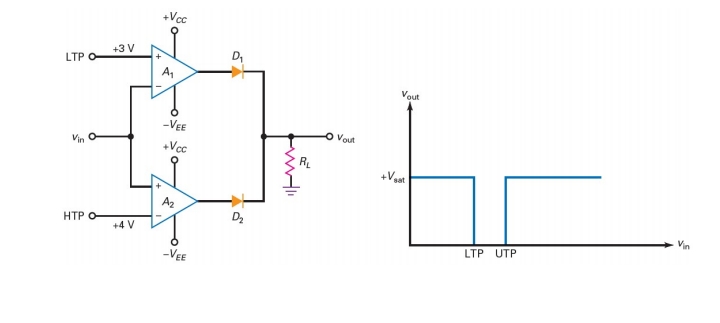

Transcribed Image Text:+Vcc
+3 V
D,
LTP O
A,
Vout
-VEE
Vout
+Vcc
R.
A2
D2
НТР О-
+4 V
LTP UTP
-VEE
Expert Solution
This question has been solved!
Explore an expertly crafted, step-by-step solution for a thorough understanding of key concepts.

This is a popular solution

Trending nowThis is a popular solution!

Step by stepSolved in 4 steps with 6 images

Knowledge Booster


Learn more about
Need a deep-dive on the concept behind this application? Look no further. Learn more about this topic, electrical-engineering and related others by exploring similar questions and additional content below.Similar questions
- c) A buck converter with constant frequency peak current mode control has Vs = 28V, V = 20V, L = 301uH, fs = 100 kHz. Find the ramp slop for the optimum compensation and the peak compensation voltage. %3Darrow_forward5. The following Data input and data select waveforms are applied to a De-Multiplexer. Determine the output waveform. Data in Spiarrow_forward5arrow_forward
- uo A:EV * ll. pluli ► b89f3244-f736-4021-901... PI EXPlain The effect of increasing The filter Capacitance on The outfut Voltage in The haif - wave rectifier and filber Circuit ? CS Scanned with CamScannerarrow_forwardQ. No 1. For the given analog signal, follow the proper steps to convert this signal to digital signal. (Take voltage levels L = 8, n= 3). Also assign proper coding to each voltage level and draw the resultant digital waveform for the given analog signal. Sample times Arnalog imput Timearrow_forward9.8. (a) Plot the even and odd parts of the signal of Figure. * In] 3. 2. ... ... -2-1 -6-5-4-3 01 2345 6arrow_forward
arrow_back_ios
arrow_forward_ios
Recommended textbooks for you
- Introductory Circuit Analysis (13th Edition)Electrical EngineeringISBN:9780133923605Author:Robert L. BoylestadPublisher:PEARSON
 Delmar's Standard Textbook Of ElectricityElectrical EngineeringISBN:9781337900348Author:Stephen L. HermanPublisher:Cengage Learning
 Programmable Logic ControllersElectrical EngineeringISBN:9780073373843Author:Frank D. PetruzellaPublisher:McGraw-Hill Education
  Fundamentals of Electric CircuitsElectrical EngineeringISBN:9780078028229Author:Charles K Alexander, Matthew SadikuPublisher:McGraw-Hill Education
 Electric Circuits. (11th Edition)Electrical EngineeringISBN:9780134746968Author:James W. Nilsson, Susan RiedelPublisher:PEARSON
 Engineering ElectromagneticsElectrical EngineeringISBN:9780078028151Author:Hayt, William H. (william Hart), Jr, BUCK, John A.Publisher:Mcgraw-hill Education,
Introductory Circuit Analysis (13th Edition)
Electrical Engineering
ISBN:9780133923605
Author:Robert L. Boylestad
Publisher:PEARSON
Delmar's Standard Textbook Of Electricity
Electrical Engineering
ISBN:9781337900348
Author:Stephen L. Herman
Publisher:Cengage Learning
Programmable Logic Controllers
Electrical Engineering
ISBN:9780073373843
Author:Frank D. Petruzella
Publisher:McGraw-Hill Education
Fundamentals of Electric Circuits
Electrical Engineering
ISBN:9780078028229
Author:Charles K Alexander, Matthew Sadiku
Publisher:McGraw-Hill Education
Electric Circuits. (11th Edition)
Electrical Engineering
ISBN:9780134746968
Author:James W. Nilsson, Susan Riedel
Publisher:PEARSON
Engineering Electromagnetics
Electrical Engineering
ISBN:9780078028151
Author:Hayt, William H. (william Hart), Jr, BUCK, John A.
Publisher:Mcgraw-hill Education,