
Elements Of Electromagnetics
7th Edition
ISBN: 9780190698614
Author: Sadiku, Matthew N. O.
Publisher: Oxford University Press
expand_more
expand_more
format_list_bulleted
Related questions
Question
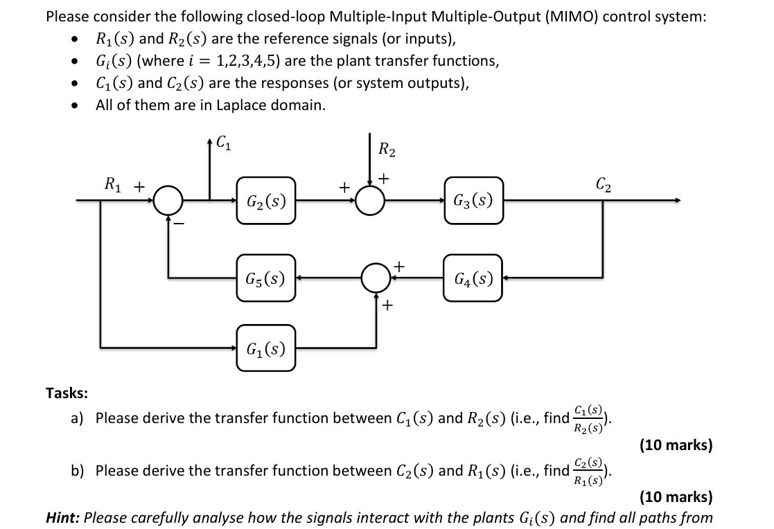

Transcribed Image Text:Please consider the following closed-loop Multiple-Input Multiple-Output (MIMO) control system:
R₁(s) and R2(s) are the reference signals (or inputs),
•
G₁(s) (where i = 1,2,3,4,5) are the plant transfer functions,
•
C₁(s) and C2(s) are the responses (or system outputs),
•
All of them are in Laplace domain.
R2
+
R₁ +
+
G₂(s)
G3(S)
Tasks:
G5(s)
G4(s)
+
G₁(s)
می
a) Please derive the transfer function between C₁ (s) and R₂(s) (i.e., find
R₂(s)
(10 marks)
(10 marks)
b) Please derive the transfer function between C₂(s) and R₁(s) (i.e., find C2 (s)).
R₁(s)
Hint: Please carefully analyse how the signals interact with the plants G₁(s) and find all paths from
Expert Solution
This question has been solved!
Explore an expertly crafted, step-by-step solution for a thorough understanding of key concepts.

Step by stepSolved in 2 steps with 2 images

Knowledge Booster

Similar questions
- Please solve this question in mechatronicsarrow_forward(1) Consider the system represented by the block diagram. The closed loop transfer function T(s)-Y(s)/R(s) is (a) T(s)-50/(s+55 s+50). (b) T(s)=10/(s+50 s+55) (c) T(s)=10/(s+55 s+10). (d) None of the above. R(s)- 10 + s+5 5 Y(s)arrow_forwardThe arm angle, e (t), is controlled by a closed-loop system. The input (reference) to the system is the desired angle, and the output is the actual angle. A controller uses the difference between the desired angle and the actual angle to drive the motor, resulting in a motor torque applied to the system. motor torque(tm) shoulder joint damping(B) Arm length (1) g The customer wants to make a system to have 1) O steady-state error 2) Less than 10% overshoot 3) Less than 1 secs of settling time For a step input. Mass(m)arrow_forward
- The arm angle, e (t), is controlled by a closed-loop system. The input (reference) to the system is the desired angle, and the output is the actual angle. A controller uses the difference between the desired angle and the actual angle to drive the motor, resulting in a motor torque applied to the system. motor torque(t) houlder joint damping(B) The customer wants to make a system to have 1) O steady-state error 2) Less than 10% overshoot 3) Less than 1- For a step inp **ling time Arm length (/) Mass(m) g design a controller to meet the design spec above. 1) Design a controller to meet the design spec. 2) Evaluate your controller using step response (time response) 3) Evaluate your closed-loop system using frequency response (e.g., Bandwidth, Gain margin. Phase margin).arrow_forwardQUESTION 5 Consider the system whose block diagram is shown below. D(s) R(s) + + C(s) K G(s) G(8) R(s) is the reference input or target, and D(s) is the disturbance input. Gp(t) is the plant (house, motor, car,...) transfer function, Gc(t) is the compensator transfer function, and K is the compensator gain given by 1 G (s) G (s) = P s+10 1 3s+2 and K=5. Find the transfer function, C(s)/R(s). 3 s²+16s+14 8 3s²+32s+25 S 382+8+6 8(s+ 10) 3s² + 32s+25 3s+2 3s²+32s+25 5 3x²+32x+25arrow_forward6. The figure below represents a time response of a control system. y(r) 0.63 What is it? a) Unit-step response of a Prototype First-Order System; b) Unit-Impulse Response of a Prototype First-Order System; c) Unit-Step Response of a Prototype Second-Order System; d) Unit-Impulse Response of a Prototype Second-Order System.arrow_forward
- QUESTION 1 Given a system model, d²x (t) dx (1) dt² dt x (0) = 1 dx (1) dt +2- +x(t) =f(t) t=0 What is the transfer function, X(s)/F(s)? O X(s) s² + s+1 F(s) 1 O X (s) F(s) O X (s) F(s) = 0. X (s) F(s) = 1 s²+2s+1 1 s²+1 S s²+2s+1arrow_forwardA) Find and plot closed-loop pole locations of the system below for K=0, 10, 25, 40, 50 B) Calculate the angles and magnitude of the open-loop transfer function for each of the poles depending on the K above. C) Plot closed loop time response for each closed loop transfer function for K = 0, 10, 25, 40, 50. D) Discuss the transient response: pole locations and time response. E) Discuss the steady-state response. R(s) + Ꮎ C Р • Controller C = K Plant P = 16 s(s + 10) Octave is allowedarrow_forwardProblem 3. Consider the electrical circuit shown in Figure 3 (left). Assume that R₁ = R2 = 1 and C = 1F. 1) (15 points) Derive the transfer function G(s) = Vo(s)/Vs(s) of the electrical circuit. 2) (15 points) If a controller is used to control the system, then the block diagram of the closed-loop system is given by Fig. 3 (right). Suppose that the reference is a ramp signal, i.e., r(t) = t 1(t). Design a controller De(s) such that the closed-loop system achieves perfect tracking (e(t) = r(t) - y(t) → 0). Justify your design. a -> + US R₁i w C: iz iz i3 + R2 Vo RO Σ Do(s) G(s) OY Figure 3: Electrical system in Problem 3.arrow_forward
- Below is a very common feedback block system. It is a 1dof, and unity-feedback system. The input is the reference command R(s). This is what flows out of thin air, into the system. All other signals in the system (e.g. U, Y, etc.) will depend on R(s). R(s) a. E(s) e. K U(s) G Y(s) Write the algebraic relation between the output Y(s) and the reference R(s) in terms of G and K?. Write it in the format Y = some function of s * R b. What is the TF from R to Y, aka the closed loop TF? What is the "Loop TF" aka the "the open-loop TF"? G has zeros at ZG1, ZG2 etc. and poles at PG1, PG2 etc. C. K has zeros at ZK1, ZK2 etc. and poles at PK1, PK2 etc. What are the zeros and the poles of OLTF? What are the zeros and the poles of CLTF? d. Write the algebraic relation between the error E(s)=R-Y and the reference R(s) in terms of G and K? Write it in the format E = some function of s * R. What is the TF from R to E? Write the algebraic relation between the controller output U(s) and the reference…arrow_forwardWe consider a dynamical system represented by the block diagram: Simple negative feedback: U(s) E(s) input, + with T₁(s) T₂(s) = 2 = a 1+5² T,(s) T₂(s) X(S) output measurement with a 4 and Calculate the closed-loop transfer function at s=10.arrow_forwardasaparrow_forward
arrow_back_ios
SEE MORE QUESTIONS
arrow_forward_ios
Recommended textbooks for you
- Elements Of ElectromagneticsMechanical EngineeringISBN:9780190698614Author:Sadiku, Matthew N. O.Publisher:Oxford University Press
 Mechanics of Materials (10th Edition)Mechanical EngineeringISBN:9780134319650Author:Russell C. HibbelerPublisher:PEARSON
 Thermodynamics: An Engineering ApproachMechanical EngineeringISBN:9781259822674Author:Yunus A. Cengel Dr., Michael A. BolesPublisher:McGraw-Hill Education
  Control Systems EngineeringMechanical EngineeringISBN:9781118170519Author:Norman S. NisePublisher:WILEY
 Mechanics of Materials (MindTap Course List)Mechanical EngineeringISBN:9781337093347Author:Barry J. Goodno, James M. GerePublisher:Cengage Learning
 Engineering Mechanics: StaticsMechanical EngineeringISBN:9781118807330Author:James L. Meriam, L. G. Kraige, J. N. BoltonPublisher:WILEY
Elements Of Electromagnetics
Mechanical Engineering
ISBN:9780190698614
Author:Sadiku, Matthew N. O.
Publisher:Oxford University Press
Mechanics of Materials (10th Edition)
Mechanical Engineering
ISBN:9780134319650
Author:Russell C. Hibbeler
Publisher:PEARSON
Thermodynamics: An Engineering Approach
Mechanical Engineering
ISBN:9781259822674
Author:Yunus A. Cengel Dr., Michael A. Boles
Publisher:McGraw-Hill Education
Control Systems Engineering
Mechanical Engineering
ISBN:9781118170519
Author:Norman S. Nise
Publisher:WILEY
Mechanics of Materials (MindTap Course List)
Mechanical Engineering
ISBN:9781337093347
Author:Barry J. Goodno, James M. Gere
Publisher:Cengage Learning
Engineering Mechanics: Statics
Mechanical Engineering
ISBN:9781118807330
Author:James L. Meriam, L. G. Kraige, J. N. Bolton
Publisher:WILEY