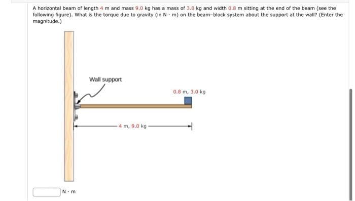
A horizontal beam of length 4 m and mass 9.0 kg has a mass of 3.0 kg and width 0.8 m sitting at the end of the beam (see the following figure). What is the torque due to gravity (in N - m) on the beam-block system about the support at the wall? (Enter the magnitude.) Wall support 0.8 m, 3.0 kg 4 m, 9.0 kg N-m


Q: The system in the figure consists of AB copper bars with a diameter of 30 mm and BC aluminum bars…
A:
Q: Draw the shear-force and bending-moment diagrams for a simple beam as shown in Figure Q2 with a…
A:
Q: Q4/ For the beam shown in Fig.2, if the modulus of elasticity (E) equal to 200 GPa, by using Moment-…
A: A moment is a movement of the body when a body is rotating on an axis. The moment is also known as…
Q: A beam segment subjected to internal bending moments at sections A and B is shown along with a…
A:
Q: A stepped shaft ABC consisting of two solid,circular segments is subjected to uniformly…
A: Write the given data in the problem. d1=57 mm d2=44 mm L1=0.75 m L2=0.50 m t1=3100 N·m/mT2=1100…
Q: A loaded, simply supported beam and its cross-section are shown in the figures below. 5 kN/m 20 mm:…
A: Solution:
Q: Q3: Draw the shear force and bending moment diagrams for the loaded beam shown (see figure below). (…
A: Draw the free-body diagram of the beam.
Q: Q4/ For the beam shown in Fig.2, if the modulus of elasticity (E) equal to 200 GPa, by using Moment-…
A:
Q: La7 For the simply supported beam and the loading shown in the figure find the * Chinge forces (B)…
A: It is required to determine support reaction force
Q: In the following figure, a uniform beam of length 6.00 meters is supported by a horizontal cable and…
A:
Q: Hinge supported beam is loaded by two concentrated forces and a couple. M F, F2 1 Given: /4=20cm;…
A:
Q: The overhanging beam is supported by a pin at A and the two-force strut BC as shown in Figure Q4.1.…
A:
Q: The embedded cone of height h and circular base (radius R) in the figure is subjected to the strut…
A: Axial force, shear forces, bending moments and torsional moments due to the loading needs to be…
Q: 8 em cm 1 cm 8icm 1 m 2m 1m Prob. 11.9
A:
Q: Let's consider a fixed supported beam subjected to a triangular distributed load as shown in the…
A: Given:
Q: Cantilever beam is loaded by three concentrated forces. F2 F3 Given: 1 1 = 13cm; l 2 = 20cm; 1 3 =…
A:
Q: A uniform, horizontal beam of mass M 30 kg and length L its left end, as in the figure. The beam is…
A: Find the maximum mass of box.
Q: Consider the metallic structure composed of two homogeneous beams connected by a C joint, with the…
A: given overhanging beam
Q: The maximum bending stress at distance 0.5 m from the built-in right hand end in the structural beam…
A:
Q: The beam with triangular section L = 180 cm long shown in the figure is forced to bend with a…
A: Given: Maximum stress is 3600 daN/cm2. q=4.5 daN/cm Length of the beam is 180 cm. b=6 cm Factor of…
Q: For the system shown in the figure, find the maximum internal shear force in kN. Hint: you will need…
A:
Q: A bridge of length l = 60.0m and mass M = 10% kg is supported on a smooth pier at each end as shown…
A: Data given- l = 60 m M = 105 kg m = 104 kg d = 20 m
Q: Q2: For the beam shown in figure below, find the bending stress of beam at point A. When I= 120*10*…
A: Bending equation is given as: MI=σy=ER where, M is the bending moment I is the moment of…
Q: A beam subjected to a bending test has internal vertical shear force V=2000N. The cross-sectional…
A:
Q: 50 kN 30 kN A 2 m 1 m 3 m
A: For solution refer below images.
Q: Calculate and draw the shear force and Bending moment diagram of the following figure. Note Ra and…
A:
Q: A beam is subjected to a distributed load and a concentrated force F (magnitude 400 N) at the end of…
A:
Q: aw the Normal Force Diagram. (b) Draw the shear force diagram. (c) Draw the bending moment…
A:
Q: 7) Consider the beam in the figure below. Take w=50 kN/m. The 40 kN force makes an angle of 60…
A:
Q: Choose the mass M in the figure with a value that does not end with zero from 302 to 497 kg. Find…
A:
Q: 3-In the figure given below, P(load) and M(moment) effects from the mid point of the fixed beam from…
A: Both ends of a fixed or built-in beam are firmly fastened, ensuring that the slope at the ends…
Q: Under cruising conditions, the distributed load acting on the wing of a small airplane has the…
A:
Q: Cantilever beam is loaded by three concentrated forces. F, F, F, 2 3 Given: 11 = 10cm; 1 2 = 25cm; l…
A:
Q: 40 N.m Da 0.5 m 280 N.m 150 N.m 2 0.3 m 0.4 m
A:
Q: Q.2. A beam ABC with an overhang at one end supports a uniform load of intensity 12 kN/m and a…
A:
Q: A bridge of length 50.0 m and mass 7.60 of mass 3.30 x 10⁴ kg is located 15.0 m from one end. What…
A:
Q: For the concentrated load shown in * :the figure. find the reaction RB 50 kN A B 10 m the figure.…
A:
Q: For the simply supported beam in figure, the shear force at midspan equals: 80 kN 80 kN 2 4 m Select…
A: Given, External force = 80 kN
Q: A fiberglass pipe is lifted by a sling, as shown in the figure. The outerdiameter of the pipe is 6,0…
A: Given data as per question Outer diameter of pipe =6 in thickness=0.25 in weight density =0.053…
Q: Lets consider a simple supported beam subjected to a triangular distributed load and a couple moment…
A:
Q: Consider the figure shown below where F = 200 N and P = 100 N. What is the net moment at point C?
A:
Q: 5 kN/m 3 cm Q.3 Find the maximum compression and tension beam stress for the cross section as figure…
A: The center of gravity of the given figure is calculated as: y=A1y1+A2y2A1+A2 here, A1 represents…
Q: 25. A fiberglass pipe is lifted by a sling, as shown in the figure. The outer diameter of the pipe…
A: Given data as per questionLength of pipe =10 ms=4 md2=100 mmd1=100−12=88 mmweight density =1500…
Q: m of a shaft with a length L = 3.5 m shown in the figure is hollow.Shaft τsafe =100 MPa, ωsafe =0,25…
A: Consider the Free body diagram: Moment acting on DE=MMoment acting on CD=M+2M =3MMoment acting on…
Q: points A, B and D, respectively, as shown in the figure. A uniformly distributed loac of 4 kN/m…
A:
Q: 3-In the figure given below, P(load) and M(moment) effects from the mid point of the fixed beam from…
A:
Q: Problem 4: A barge shown in the figure carries 290kN/m and 580KN/m loads. 3m 6m Зт 580 kN/m a. Find…
A: The given beam is as shown below, Let the upward load acting on the beam is w, (a) Balancing…
Q: Question 1) In the beam whose loading condition is given in the figure, F force F= 79 kN, w1…
A:
Q: (a) Figure Q4(a). The structural members each has a cross sectional area A, elastic modulus E, shear…
A: (a)U=?A-AreaE-Elastic modulusG-Shear ModulusI-Moment of InertiaJ-Polar moment of Inertia ***As per…


Trending now
This is a popular solution!

Step by step
Solved in 2 steps with 1 images


- A non prism elk- bar ABC made up of segments AB(length £,, cross-sectional area .Inland BC (length i-,, cross-sectional area A2) is fixed at end A and free al end C (see figure). The modulus of elasticity of the bar is E. A small gap of d intension s exists between the end of the bar and an elastic spring of length Lj and spring constant k3. If bar ABC only (not tin? spring} is subjected to temperature increase A3", determine the following. (a) Write an expression for reaction forces R^ and RDif the elongation of /I BC exceeds gap length s. (b) Find expressions for the displacements of points B and C if the elongation of ABC exceeds gap length s..2 A ligmio.irc ii supported by two vorlical beams consistins: of thin-walled, tapered circular lubes (see ligure part at. for purposes of this analysis, each beam may be represented as a cantilever AB of length L = 8.0 m subjected to a lateral load P = 2.4 kN at the free end. The tubes have a constant thickness ; = 10.0 mm and average diameters dA = 90 mm and dB = 270 mm at ends A and B, re s pec lively. Because the thickness is small compared to the diameters, the moment of inerlia at any cross section may be obtained from the formula / = jrrf3;/8 (see Case 22, Appendix E); therefore, the section modulus mav be obtained from the formula S = trdhlA. (a) At what dislance A from the free end docs the maximum bending stress occur? What is the magnitude trllul of the maximum bending stress? What is the ratio of the maximum stress to the largest stress (b) Repeat part (a) if concentrated load P is applied upward at A and downward uniform load q {-x) = 2PIL is applied over the entire beam as shown in the figure part b What is the ratio of the maximum stress to the stress at the location of maximum moment?Find expressions for shear force V and moment M at v = L/2 of beam AB in structure (a). Express V and M in terms of peak load intensity q0and beam length variable L. Repeat for structure (b) but find Fand M at m id-span of member BC.
- A fiberglass pipe is lifted by a sling, as shown in the figure. The outerdiameter of the pipe is 6,0 in., its thickness is 0.25 in,, and its weightdensity is 0,053 1b/in3 the length of the pipe is L = 36 ft and the distancebetween lifting points is s = 11 ft.a. Determine the maximum bending stress in the pipe due to its ownweight,b. Find the spacing s between lift points which minimizes thebending stress. What is the minimum bebding stress?c. What spacing s leads to maximum bending stress? What is thatstress?N for Newton, m for meter, mm for millimeter, N/(mm^2) for Stress, mm^2 or m^2 for Area, mm^4 for Moment of inertia and Nm for bending moment. Use brackets if the power is MINUS for Example: 0.00125 N =1.25*10^(-3)N. A simply supported beam AB = 11 m has a hollow rectangular cross-section with 14 cm as width, 29 cm as depth and inner thickness as 1 cm is subjected to a point load of 6 N & 8 N acting at C and D respectively and a uniformly distributed load (UDL) of 8 N/m starts from mid-span and ends at the right support of the beam. Determine the maximum bending stress and the bending stress at 1 cm from the top. Take AC = 1 m & CD = 2 m. Solution: i) Reaction force at B = ii) Reaction Force at A = iii) The distance from B at which the shear Force value changes from "-" to "+" = iv) Maximum Bending Moment (Please write the Maximum bending moment valve in "Nm") = v) Moment of Inertia, I = vi) Maximum bending stress = vii) Bending stress at 1 cm from…N for Newton, m for meter, mm for millimeter, N/(mm^2) for Stress, mm^2 or m^2 for Area, mm^4 for Moment of inertia and Nm for bending moment. Use brackets if the power is MINUS for Example: 0.00125 N =1.25*10^(-3)N. A simply supported beam AB = 11 m has a hollow rectangular cross-section with 14 cm as width, 29 cm as depth and inner thickness as 1 cm is subjected to a point load of 6 N & 8 N acting at C and D respectively and a uniformly distributed load (UDL) of 8 N/m starts from mid-span and ends at the right support of the beam. Determine the maximum bending stress and the bending stress at 1 cm from the top. Take AC = 1 m & CD = 2 m. Solution: i) Reaction force at B = ii) Reaction Force at A = iii) The distance from B at which the shear Force value changes from "-" to "+" = Answer and unit for part 3 iv) Maximum Bending Moment (Please write the Maximum bending moment valve in "Nm") = v) Moment of Inertia, I = vi) Maximum bending stress = vii)…
- N for Newton, m for meter, mm for millimeter, N/(mm^2) for Stress, mm^2 or m^2 for Area, mm^4 for Moment of inertia and Nm for bending moment. Use brackets if the power is MINUS for Example: 0.00125 N =1.25*10^(-3)N. A beam has a bending moment of 3 kN-m applied to a section with a hollow circular cross-section of external diameter 3.4 cm and internal diameter 2.4 cm . The modulus of elasticity for the material is 210 x 109 N/m2. Calculate the radius of curvature and maximum bending stress. Also, calculate the stress at the point at 0.6 cm from the neutral axis Solution: (i) The moment of inertia = ii) The radius of curvature is (iii) The maximum bending stress is iv) The bending stress at the point 0.6 cm from the neutral axis is3) The force, FT = 1 kN, and moment, MT = 0.5 kN-m, at the tip are caused by a wing tip vortexand a winglet, not shown. L = 12 m and the spar has an elastic modulus of E = 70 GPa and aPoisson’s ratio of n = 0.33. The mass of the wing is 4000 kg, and the weight of the engine is 107kN. Use 9.8 m/s 2 for the acceleration due to gravity.Consider the cross-section shown (you can look these up). Pay attention to the coordinate systemgiven in the drawing.d) where is the centroid?e) what is the area?f) Calculate the shear modulus3) The force, FT = 1 kN, and moment, MT = 0.5 kN-m, at the tip are caused by a wing tip vortexand a winglet, not shown. L = 12 m and the spar has an elastic modulus of E = 70 GPa and aPoisson’s ratio of n = 0.33. The mass of the wing is 4000 kg, and the weight of the engine is 107kN. Use 9.8 m/s 2 for the acceleration due to gravity.Consider the cross-section shown (you can look these up). Pay attention to the coordinate systemgiven in the drawing.g) Compute each of these moments of inertia with the values b = 0.4 m, d =0.5 m , t =0.1 m.
- 3) The force, FT = 1 kN, and moment, MT = 0.5 kN-m, at the tip are caused by a wing tip vortexand a winglet, not shown. L = 12 m and the spar has an elastic modulus of E = 70 GPa and aPoisson’s ratio of n = 0.33. The mass of the wing is 4000 kg, and the weight of the engine is 107kN. Use 9.8 m/s 2 for the acceleration due to gravity.Consider the cross-section shown (you can look these up). Pay attention to the coordinate systemgiven in the drawing.a) what is the moment of inertia about y-axis in terms of the symbolic dimensions shown?b) what is the moment of inertia about z-axis in terms of the symbolic dimensions shown?c) what is the polar moment of inertia in terms of the symbolic dimensions shown (i.e.about the x-axis)?d) where is the centroid?e) what is the area?f) Calculate the shear modulusg) Compute each of these moments of inertia with the values b = 0.4 m, d =0.5 m , t =0.1 m.nonuniform beam 4.50 m long and weighing 1.40 kNmakes an angle of 25.0° below the horizontal. It is held in position bya frictionless pivot at its upper right end and by a cable 3.00 m fartherdown the beam and perpendicular to it . The center ofgravity of the beam is 2.00 m down the beam from the pivot. Lightingequipment exerts a 5.00 kN downward force on the lower left end ofthe beam. Find the tension T in the cable and the horizontal and verticalcomponents of the force exerted on the beam by the pivot. Start bysketching a free-body diagram of the beam.A shaft having length equal to 10 m and diameter equal to (50+ 01) mm is simply supported at both ends. The shatt carries four masses (150 + 01) kg, (200 + 01) kg, (250 +01) kg and (300 + 01) kg. These masses are located at a distance of 1.5m, 2.5 m, 5.5 mand 7.5 m from the left hand side support, respectively. The modulus of elasticity, E, for the material of the shaft is 200 GN/m? and mass density for the shaft material is 7500 kg/m?3. Determine critical speed of the shaft in revolutions per minute for the following two cases: 1. Effect of the mass of the shaft is neglected. 2. Effect of the mass of the shaft is considered. What is the usefulness of the answers determined in this problem?