Problem 3: Now suppose one adds a resistor, R, to the circuit as shown on the right. Assume that Vs= 0 V, VDp = 1 V and R = 1 k2. Assume that the MOSFET has VT M1 R VG. VD :0.5 V and can be assumed to VOUT Vod either be OFF or be a switched resistor Vs with an on resistance of 100 Q. Solve for VoUT when (a) VG (b) VG = 1.2 V. For each part, first draw the equivalent circuit (simplifying as many elements as you can), then solve 0.4 V, +1 +1
Problem 3: Now suppose one adds a resistor, R, to the circuit as shown on the right. Assume that Vs= 0 V, VDp = 1 V and R = 1 k2. Assume that the MOSFET has VT M1 R VG. VD :0.5 V and can be assumed to VOUT Vod either be OFF or be a switched resistor Vs with an on resistance of 100 Q. Solve for VoUT when (a) VG (b) VG = 1.2 V. For each part, first draw the equivalent circuit (simplifying as many elements as you can), then solve 0.4 V, +1 +1

Power System Analysis and Design (MindTap Course List)
6th Edition
ISBN:9781305632134
Author:J. Duncan Glover, Thomas Overbye, Mulukutla S. Sarma
Publisher:J. Duncan Glover, Thomas Overbye, Mulukutla S. Sarma
Chapter3: Power Transformers
Section: Chapter Questions
Problem 3.30P: Reconsider Problem 3.29. If Va,VbandVc are a negative-sequence set, how would the voltage and...

Related questions
Question

Transcribed Image Text:Problem 3:
Now suppose one adds a resistor, R, to
the circuit as shown on the right.
Assume that Vs= 0 V, VDp = 1 V and
R = 1 k2. Assume that the MOSFET
has VT
M1
R
VG.
VD
:0.5 V and can be assumed to
VOUT Vod
either be OFF or be a switched resistor
Vs
with an on resistance of 100 Q. Solve
for VoUT when (a) VG
(b) VG = 1.2 V. For each part, first draw
the equivalent circuit (simplifying as
many elements as you can), then solve
0.4 V,
+1
+1
Expert Solution
Step 1
Part (a):
Case 1:
The condition for the saturation is given by:
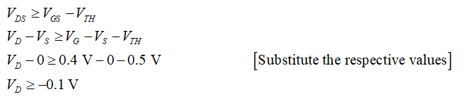
Step 2
The equivalent circuit diagram for this condition:
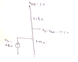
Step 3
For the saturation region, the voltage at the drain terminal will be equal to the output voltage. Thus, the output voltage will be -0.1 V.
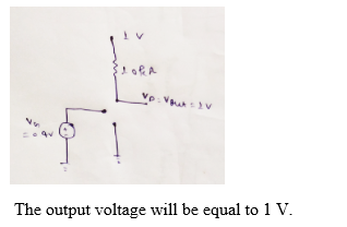
Case 2:
Consider the MOSFET is OFF.
The equivalent circuit diagram for this condition is shown in the below figure:

Step by step
Solved in 6 steps with 6 images

Knowledge Booster


Learn more about
Need a deep-dive on the concept behind this application? Look no further. Learn more about this topic, electrical-engineering and related others by exploring similar questions and additional content below.Recommended textbooks for you
Power System Analysis and Design (MindTap Course …
Electrical Engineering
ISBN:
9781305632134
Author:
J. Duncan Glover, Thomas Overbye, Mulukutla S. Sarma
Publisher:
Cengage Learning
Power System Analysis and Design (MindTap Course …
Electrical Engineering
ISBN:
9781305632134
Author:
J. Duncan Glover, Thomas Overbye, Mulukutla S. Sarma
Publisher:
Cengage Learning