Q1/The data in table below for the system shown, if there is a 3phase fault occurs at bus 3,find the fault current using bus impedance matrix. MVA 100 voltage 33kv XI (р.0) 0.2 clement G1 G2 By use bus impedance matrix method 100 33kv 0.2 TI 100 33/220 kv 0.05 T2 100 33/ 220 kv 0.05 L1 L2 100 100 220 kv 220 kv 220 kv 0.1 0.1 L3 100 0.1 T LI Te GL) A Le L3
Q1/The data in table below for the system shown, if there is a 3phase fault occurs at bus 3,find the fault current using bus impedance matrix. MVA 100 voltage 33kv XI (р.0) 0.2 clement G1 G2 By use bus impedance matrix method 100 33kv 0.2 TI 100 33/220 kv 0.05 T2 100 33/ 220 kv 0.05 L1 L2 100 100 220 kv 220 kv 220 kv 0.1 0.1 L3 100 0.1 T LI Te GL) A Le L3

Power System Analysis and Design (MindTap Course List)
6th Edition
ISBN:9781305632134
Author:J. Duncan Glover, Thomas Overbye, Mulukutla S. Sarma
Publisher:J. Duncan Glover, Thomas Overbye, Mulukutla S. Sarma
Chapter2: Fundamentals
Section: Chapter Questions
Problem 2.38P

Related questions
Question
P1
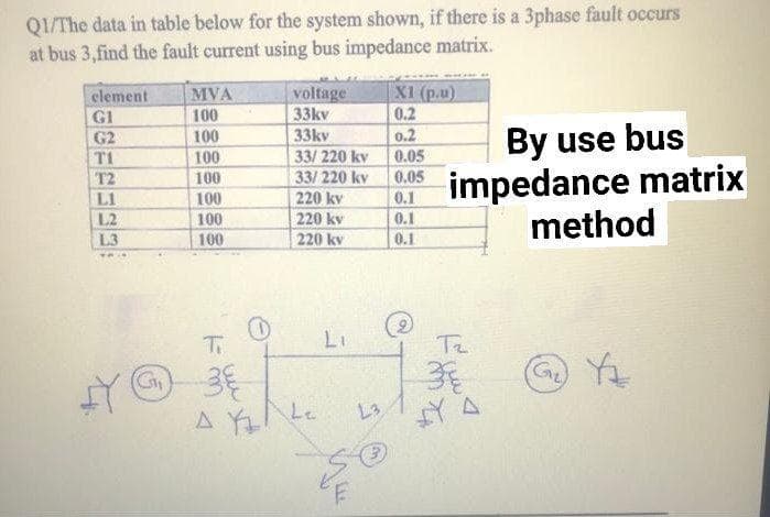
Transcribed Image Text:Q1/The data in table below for the system shown, if there is a 3phase fault occurs
at bus 3,find the fault current using bus impedance matrix.
MVA
100
100
voltage
33kv
X1 (p.u)
0.2
element
G1
G2
By use bus
impedance matrix
method
33kv
0.2
33/220 kv
33/ 220 kv
220 kv
220 kv
220 kv
T1
100
0.05
T2
100
0.05
100
100
0.1
L1
L2
0.1
L3
100
0.1
Ti
LI
Ta
G Y
L3
A Le
Expert Solution
This question has been solved!
Explore an expertly crafted, step-by-step solution for a thorough understanding of key concepts.

Step by step
Solved in 2 steps with 2 images

Knowledge Booster


Learn more about
Need a deep-dive on the concept behind this application? Look no further. Learn more about this topic, electrical-engineering and related others by exploring similar questions and additional content below.Recommended textbooks for you
Power System Analysis and Design (MindTap Course …
Electrical Engineering
ISBN:
9781305632134
Author:
J. Duncan Glover, Thomas Overbye, Mulukutla S. Sarma
Publisher:
Cengage Learning
Power System Analysis and Design (MindTap Course …
Electrical Engineering
ISBN:
9781305632134
Author:
J. Duncan Glover, Thomas Overbye, Mulukutla S. Sarma
Publisher:
Cengage Learning