Q2) The battery charger in the figure below includes a fully controlled single-phase bridge rectifier from a 50 Hz source. Powered by 200 V peak. Battery model includes 100 V voltage source series connection and resistor is12.Assuming uniformity, find a relation for the battery charging current in terms of angle a. L Batterymodel 10mH 10 v, =Vm sinøt 100
Q2) The battery charger in the figure below includes a fully controlled single-phase bridge rectifier from a 50 Hz source. Powered by 200 V peak. Battery model includes 100 V voltage source series connection and resistor is12.Assuming uniformity, find a relation for the battery charging current in terms of angle a. L Batterymodel 10mH 10 v, =Vm sinøt 100

Introductory Circuit Analysis (13th Edition)
13th Edition
ISBN:9780133923605
Author:Robert L. Boylestad
Publisher:Robert L. Boylestad
Chapter1: Introduction
Section: Chapter Questions
Problem 1P: Visit your local library (at school or home) and describe the extent to which it provides literature...

Related questions

Question
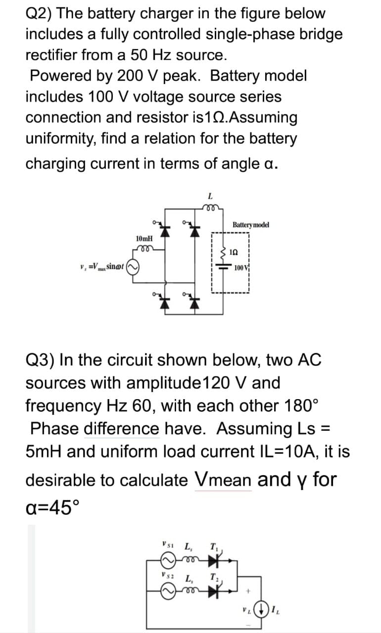
Transcribed Image Text:Q2) The battery charger in the figure below
includes a fully controlled single-phase bridge
rectifier from a 50 Hz source.
Powered by 200 V peak. Battery model
includes 100 V voltage source series
connection and resistor is12.Assuming
uniformity, find a relation for the battery
charging current in terms of angle a.
L.
Battery model
10mH
10
v, =V sin@t
100 V
Q3) In the circuit shown below, two AC
sources with amplitude120 V and
frequency Hz 60, with each other 180°
Phase difference have. Assuming Ls :
5mH and uniform load current IL=10A, it is
desirable to calculate Vmean and y for
a=45°
V51
L,
T
le
V s2
L,
Expert Solution
This question has been solved!
Explore an expertly crafted, step-by-step solution for a thorough understanding of key concepts.

Step by step
Solved in 2 steps with 2 images

Knowledge Booster


Learn more about
Need a deep-dive on the concept behind this application? Look no further. Learn more about this topic, electrical-engineering and related others by exploring similar questions and additional content below.Recommended textbooks for you
Introductory Circuit Analysis (13th Edition)
Electrical Engineering
ISBN:
9780133923605
Author:
Robert L. Boylestad
Publisher:
PEARSON

Delmar's Standard Textbook Of Electricity
Electrical Engineering
ISBN:
9781337900348
Author:
Stephen L. Herman
Publisher:
Cengage Learning

Programmable Logic Controllers
Electrical Engineering
ISBN:
9780073373843
Author:
Frank D. Petruzella
Publisher:
McGraw-Hill Education
Introductory Circuit Analysis (13th Edition)
Electrical Engineering
ISBN:
9780133923605
Author:
Robert L. Boylestad
Publisher:
PEARSON
Delmar's Standard Textbook Of Electricity
Electrical Engineering
ISBN:
9781337900348
Author:
Stephen L. Herman
Publisher:
Cengage Learning
Programmable Logic Controllers
Electrical Engineering
ISBN:
9780073373843
Author:
Frank D. Petruzella
Publisher:
McGraw-Hill Education

Fundamentals of Electric Circuits
Electrical Engineering
ISBN:
9780078028229
Author:
Charles K Alexander, Matthew Sadiku
Publisher:
McGraw-Hill Education

Electric Circuits. (11th Edition)
Electrical Engineering
ISBN:
9780134746968
Author:
James W. Nilsson, Susan Riedel
Publisher:
PEARSON

Engineering Electromagnetics
Electrical Engineering
ISBN:
9780078028151
Author:
Hayt, William H. (william Hart), Jr, BUCK, John A.
Publisher:
Mcgraw-hill Education,