QS. Figure Q5 shows an AC source G having an effective voltage of 240 V, 60 Hz is connected to a single-phase full-wave rectifier. The resistance for R is 53 2 and ripple-to-ripple current is 15%. (a) Explain the consequences of removing the inductor and reversing Bị and B2 diodes. Sketch the output voltage waveform.
QS. Figure Q5 shows an AC source G having an effective voltage of 240 V, 60 Hz is connected to a single-phase full-wave rectifier. The resistance for R is 53 2 and ripple-to-ripple current is 15%. (a) Explain the consequences of removing the inductor and reversing Bị and B2 diodes. Sketch the output voltage waveform.

Introductory Circuit Analysis (13th Edition)
13th Edition
ISBN:9780133923605
Author:Robert L. Boylestad
Publisher:Robert L. Boylestad
Chapter1: Introduction
Section: Chapter Questions
Problem 1P: Visit your local library (at school or home) and describe the extent to which it provides literature...

Related questions

Question
Answer a,b,c,d
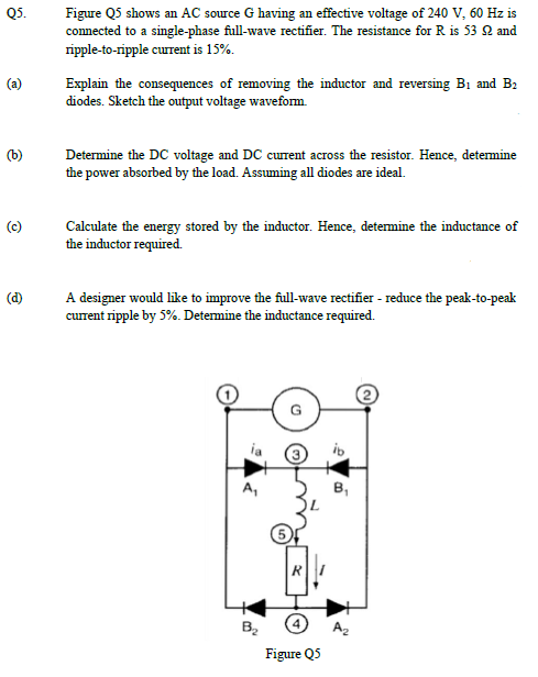
Transcribed Image Text:Figure Q5 shows an AC source G having an effective voltage of 240 V, 60 Hz is
connected to a single-phase full-wave rectifier. The resistance for R is 53 Q and
ripple-to-ripple current is 15%.
Explain the consequences of removing the inductor and reversing Bị and B2
diodes. Sketch the output voltage waveform.
(b)
Determine the DC voltage and DC current across the resistor. Hence, determine
the power absorbed by the load. Assuming all diodes are ideal.
(c)
Calculate the energy stored by the inductor. Hence, determine the inductance of
the inductor required.
A designer would like to improve the full-wave rectifier - reduce the peak-to-peak
current ripple by 5%. Determine the inductance required.
A,
B,
Figure Q5
Expert Solution
This question has been solved!
Explore an expertly crafted, step-by-step solution for a thorough understanding of key concepts.

This is a popular solution!

Trending now
This is a popular solution!

Step by step
Solved in 3 steps with 1 images

Knowledge Booster


Learn more about
Need a deep-dive on the concept behind this application? Look no further. Learn more about this topic, electrical-engineering and related others by exploring similar questions and additional content below.Recommended textbooks for you
Introductory Circuit Analysis (13th Edition)
Electrical Engineering
ISBN:
9780133923605
Author:
Robert L. Boylestad
Publisher:
PEARSON

Delmar's Standard Textbook Of Electricity
Electrical Engineering
ISBN:
9781337900348
Author:
Stephen L. Herman
Publisher:
Cengage Learning

Programmable Logic Controllers
Electrical Engineering
ISBN:
9780073373843
Author:
Frank D. Petruzella
Publisher:
McGraw-Hill Education
Introductory Circuit Analysis (13th Edition)
Electrical Engineering
ISBN:
9780133923605
Author:
Robert L. Boylestad
Publisher:
PEARSON
Delmar's Standard Textbook Of Electricity
Electrical Engineering
ISBN:
9781337900348
Author:
Stephen L. Herman
Publisher:
Cengage Learning
Programmable Logic Controllers
Electrical Engineering
ISBN:
9780073373843
Author:
Frank D. Petruzella
Publisher:
McGraw-Hill Education

Fundamentals of Electric Circuits
Electrical Engineering
ISBN:
9780078028229
Author:
Charles K Alexander, Matthew Sadiku
Publisher:
McGraw-Hill Education

Electric Circuits. (11th Edition)
Electrical Engineering
ISBN:
9780134746968
Author:
James W. Nilsson, Susan Riedel
Publisher:
PEARSON

Engineering Electromagnetics
Electrical Engineering
ISBN:
9780078028151
Author:
Hayt, William H. (william Hart), Jr, BUCK, John A.
Publisher:
Mcgraw-hill Education,