Question 5 
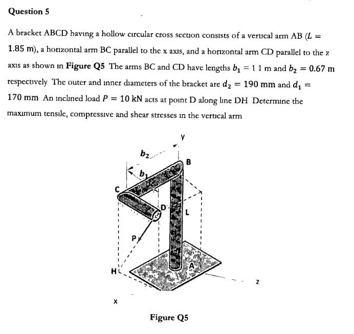
A bracket ABCD having a hollow cırcular cross sectuon consists of a vertical arm AB (L = 1.85 m), a horzontal arm BC parallel to the x axis, and a horzontal arm CD parallel to the z axis as shown in Figure Q5 The arms BC and CD have lengths b 1 1 m and b2 0.67 m = respectively The outer and inner diameters of the bracket are d2 190 mm and di = 170 mm An inclined load P 10 kN acts at point D along line DH Determine the tensile, compressive and shear stresses maximum in the vertical arm Y b2 B C HC X Figure Q5
Q: The L-bar shown in the figure is fastened by a bearing at point A that allows it to rotate, such…
A: Given F=800NRBmax=600N
Q: Eight steel cables (with equal distance to each other) are supporting a circular heavy moulding of…
A: As it is not mentioned that which three parts need to be solved, please find solutions of first…
Q: Situation 5: A segment of a chain link is shown in the figure. D. A. If the diameter D is equal to…
A: Solution 5: Part (a) The diameter of the chain, d = 0.25 in. Allowable tensile stress, σallow = 2.5…
Q: A 4.0-m-long steel wire has a cross-sectional area of 0.050 cm?. Its proportional limit has a value…
A:
Q: A rod is composed of an aluminum section rigidly attached between steel and bronze sections, as…
A: GIVEN DATA A COMPOSITE ROD AXIALLY LOADED GIVEN WE HAVE TO FIND STRESS IN EACH ROD Load P=3800lb…
Q: A rectangular steel block is 3 inches long in the x direction, 2 inches long in the y direction, and…
A:
Q: Q/ Find the number of steel bars for a rectangular foundation and support an interior column of…
A: A moment is a movement of the body when a body is rotating on an axis. The moment is also known as…
Q: steel rod: 0 24 mm 0.4 m 3 m Figure 1.23 A rectangular column of sides 0.4m x 0.35m, made of…
A:
Q: 2. A rigid bar ABDE is being attached to a wall via a pin at A and alloy steel rod BC (E = 250 GPa).…
A:
Q: y 960 mm? AT = -25°C 80 GPa 165 kN 15.7 x10⁻⁶/°C (1) 1920 mm? (2) A %3D B E2 160 GPa %3D 19.7…
A: Find the force in each bar and stress in each bar and deflection of point B Given data:- A1=960mm^2…
Q: Question 5 A crank arm consists of a sold segment of length bi and diameter d, a segment of length…
A: Apply force equilibrium condition along x direction.
Q: Two solid cylindrical rods AB and BC are welded together at B and loaded as shown in Figure: Q 4(b).…
A: Given, dAB = 2 in dBC = 3 in LAB = 30 in LBC = 40 in
Q: 10. / Act on the structure in Figure 4 horizontal force NK Finally, D. Find the effect of the…
A:
Q: Figure Q1 shows a composite rod ABC attached in between two rigid walls. Part AB is a solid rod made…
A:
Q: A composite shaft ABCD made of three parts is placed between two walls, as shown in Fig. 7. Part AB…
A: GIVEN: TO FIND:
Q: Question 2: The cross-sectional area for the lattice rods in the figure is A=120 mm2, the modulus of…
A: Solution
Q: An aluminum rod is rigidly attached between a steel rod and a bronze rod as shown in the figure.…
A: Answer: (1) Considering steel : P = 12600 N. (2) Considering aluminum : P = 30400 N. (3) Considering…
Q: The spar shown in the figure is wood (s.g.=0.62), 2 in by 2 in by 10 ft, and floats in sea water…
A: Buoyant force must balance the weight of wood and weight of steel for given configuration.
Q: Rigid bars AB and BCD are supported by pins A and D and by a steel rod at C. There is a roller E =…
A:
Q: block is 4 inches long in the x direction, 2 inches long in the y direction, and 3 inches long in…
A:
Q: a) Figure Q2a shows a hollow tube of rectangular cross-section subjected to an axial compressive…
A:
Q: The assembly in Figure below consists of a light rigid bar AB, pinned at O, that is attached to the…
A: Given:AB=0.75mOB=1.5m∆=5mmFor steelAst=250mm2E=200 GPaFor aluminiumL=BC=2mAal=300mm2E=70 GPaTo find…
Q: The assembly in Figure consists of a light rigid bar AB, pinned at 0, that is attached to the steel…
A:
Q: A copper tube is rigidly attached between a steel rod and an aluminum rod. Axial loads are at the…
A: Answer: (a) Steel : A = 176.4706 mm2 ; d = 14.9896 mm. (b) Copper : A = 294.7368 mm2 ; d = 19.3720…
Q: 2.) Consider the bar OA that is constrained by a ball-and-socket joint at O. Cables connect A to…
A:
Q: For question 103A and 103B, the thin-walled cylindrical container shown below. Say p is the internal…
A: Internal pressure P=15 MPa Inside diameter d=20 mm Wall thickness t=10 mm Longitudinal stress in a…
Q: QUESTION 7 Consider the circular bent rod with diameter 20 mm. The free-end of the bend is subjected…
A:
Q: SITUATION 4. Given the figure below, find the: |31 kN 5-25 mm Ф bolts 70 mm 8D mm 80 mm 70 mm T31 KN…
A:
Q: 2. The uniform beam shown in Figure 2 weighs 500N and supports a 700N load. Find the tension in the…
A: Answer: (a) The tension in the tie rope is 2899.34 N. (b) The force of the hinge on the beam is…
Q: А + 10kN 28kN 60kN 44kN 120cm 80cm Ocm 40cm Figure 1 a) Draw a Free Body Diagram for each section of…
A: Using lami's theorem TAsin1350=TCsin126.860=mgsin98.1300 TA=420.428 NTC=475.722 N Stress in each…
Q: Question 3 A Sign is supported by a pole of hollow circular cross section as shown in Figure Q3 The…
A: Calculate the force due to wind.
Q: Problem 1 An angle bracket ABC is restrained by a high strength steel wire CD, and it supports a…
A:
Q: Question 1 Determine the ground reactions at A and B of the structure in Figure QI. 20KN 3m 3m 3m…
A: Given Data: Hinge support offers two reactions . Roller support offers one reaction which is always…
Q: A copper tube is rigidly attached between a steel rod and an aluminum rod. Axial loads are at the…
A: GIVEN DATA - THREE SHAFTS CONNECTED IN SERIES AND FIXED AT RIGID SUPPORT WE HAVE TO FIND ALL POINTS…
Q: A vertical load of 1100 lb is supported by the three bars shown in the figure. Find the force in…
A:
Q: b) An aluminium rod is attached between a steel rod and a bronze rod as shown in Figure- 3. The…
A: Given data: The area of steel bar is As=550 mm2 The area of Aluminium bar is Aal=400 mm2 The area of…
Q: Question 5 A 120 mm x 100 mm x 20 mm T section short column is used as a simply supported beam. The…
A:
Q: cube 152 mm on a side is made of aluminum and suspended by string. The cube is submerged, half of it…
A:
Q: For a concrete column that is part of a braced frame, if the column is square, tied, 18 inches per…
A: Write the given data with suitable variables: a=18 in=1.5 ft12 in 1 ftL=16 ftK=1
Q: Two hollow circular rods are welded together at B and loaded as shown in Figure 5. Load P1 acting at…
A:
Q: 1) The sections and materials given in Figure 1 are different from the rod consisting of three…
A: Load ,P1=300 kNLoad, P2=200 kNClearance, δ=5 mma=1.5 mb=1 mc=0.5 mA1=20 cm2A2=15 cm2A3=10 cm2E1=70…
Q: A utility hook was formed from a round rod of diameter d= 0.75 in into the geometry shown in the…
A: The data given is, Round rod diameter, d = 0.75 in Force, F = 1500 lbf Length, L = 7 in Inner…
Q: 3. Column ABC has a uniform rectangular midpoint C is shown Figure Q3(a). Gi mm and E=70 GPa,…
A:
Q: An aluminum rod is rigidly attached between a steel rod and a bronze rod as shown in the figure…
A: GIVEN DATA- FOR STEEL AREA=500mm2 , STRESS=200MPa FOR AL AREA=400mm2 , STRESS=115MPa FOR BRONZE…
Q: The structure above is subjected to a load at point C. Using the table below, determine the forces…
A:
Q: The rigid beam shown in Figure AN- 12 is suspended by three cables. The beam is horizontal prior to…
A: Draw free body diagram of beam
Q: The loaded frame shown in Fig. 1, is supported at A (fixed support) and B (roller support). C is an…
A: a) Reaction at support A and B The free body diagram of the right part of the hinge is here, RB is…
Q: QUESTION 5: [Close-helical Spring] The deflection of the composite spring when subjected to the…
A:
Q: QUESTION 3 A steel bar AD has a cross-sectional area of 260 mm² is illustrated in Figure Q3. The…
A:
Q: IV. Question 4 Two aluminium strips and steel strip are to be bonded together to form a composite…
A:
Trending now
This is a popular solution!
Step by step
Solved in 10 steps with 10 images
- .15 A hitch-mounted bicycle rack is designed to carry up to four 30-lb bikes mounted on and strapped to two arms Gil (sec bike loads in the figure part a) The rack is attached to the vehicle at A and is assumed to be like a cant silkier beam A BCDGII (figure part b) The light of fixed segment AB is U = 10 lb. centered 9 in. from A (see figure part b) and the rest of the rack highs W2 = 40 lb. centered 19 in. from A. Segment ABCDG is a steel tube o(2 X 2 in. with a thickness I = 118 in. Segment BCDGII pivots about a bolt at B with a diameter d1 = 0.25 in. to allow access to the rear of the vehicle without removing the hitch rack. When in use, the rack is secured in an upright posit ion by a pin C(diameter o( pin d, = 5116 in.) (see phoo and figure part C). The of returning effect of the bikes on the rack is resisted by a force couple F h at BC. (a) Find the support reactions at A for the fully loaded rack. (b) Find forces in the bolt at B and the pin at C. (c) Find average shear stresses in both the bolt at Band the pin at C. (d) Find average bearing stresses o, in the bolt at B and the pin at C.A large precast concrete panel for a warehouse is raised using two sets of cables at two lift lines, as shown in the figure part a. Cable 1 has a length L1 = 22 Ft, cable 2 has a length L2= 10 ft, and the distance along the panel between lift points Band D is d = 14 ft (see figure part b). The total weight of the panel is W = 85 kips. Assuming the cable lift Forces F at each lift line are about equal, use the simplified model of one half of the panel in figure part b to perform your analysis for the lift position shown. Find the required cross-sectional area AC of the cable if its breaking stress is 91 ksi and a factor of safety of 4 with respect to failure is desired.A long re Lai nine: wall is braced by wood shores set at an angle of 30° and supported by concrete thrust blocks, as shown in the first part of the figure. The shores are evenly spaced at 3 m apart. For analysis purposes, the wall and shores are idealized as shown in the second part of the figure. Note that the base of the wall and both ends of the shores are assumed to be pinned. The pressure of the soil against the wall is assumed to be triangularly distributed, and the resultant force acting on a 3-meter length of the walls is F = 190 kN. If each shore has a 150 mm X 150 mm square cross section, what is the compressive stress
- An L-shaped reinforced concrete slab 12 Ft X 12 ft, with a 6 Ft X 6 ft cut-out and thickness t = 9.0 in, is lifted by three cables attached at O, B, and D, as shown in the figure. The cables are are combined at point Q, which is 7.0 Ft above the top of the slab and directly above the center of mass at C. Each cable has an effective cross-sectional area of Ae= 0.12 in2. (a) Find the tensile force Tr(i = 1, 2, 3) in each cable due to the weight W of the concrete slab (ignore weight of cables). (b) Find the average stress ov in each cable. (See Table I-1 in Appendix I for the weight density of reinforced concrete.) (c) Add cable AQ so that OQA is one continuous cable, with each segment having Force T, which is connected to cables BQ and DQ at point Q. Repeat parts (a) and (b). Hini: There are now three Forced equilibrium equations and one constrain equation, T1= T4.A framework ABC consists of two rigid bars AB and BC. Each having a length b (see the first part of the figure part a). The bars have pin connections at A, B, and C and are joined by a spring of stiffness k. The spring is attached at the midpoints of the bars. The framework has a pin support at A and a roller support al C, and the bars are at an angle a to the horizontal. When a vertical load P is applied at joint B (see the second part of the figure part a.) the roller support C moves to the right, the spring is stretched, and the angle of the bars decreases from a to the angle ??. (a) Determine the angle 0 and the increase S in the distance between points A and C. Also find reactions at A and C. (Use the following data: b = 200 mm. ft = 3.2 kN/m. a = 45°. and P = 50 N.) (b) Repeat part (a) if a translational spring kt= kll is added at C and a rotational spring kr= kb-l2 is added at A (see figure pan b).The L-shaped arm ABCD shown in the figure lies in a vertical plane and pivots about a horizontal pin at A. The arm has a constant cross-sectional area and total weight W. A vertical spring of stiffness k supports the arm at point B. (a) Obtain a formula for the elongation of the spring due to the weight of the arm. (b) Repeat part (a) if the pin support at A is moved to D.
- A cylindrical brick chimney of height H weighs w = 825 lb/ft of height (see figure). The inner and outer diameters are d1= 3 ft and d2= 4 ft, respectively. The wind pressure against the side of the chimney is p = 10 lb/ft2 of projected area. Determine the maximum height H if there is to be no tension in the brickwork..17 A mountain-bike rider going uphill applies torque T = Fd(F = l5lb, d = 4 in.) to the end of the handlebars ABCD by pulling on the handlebar extenders DE. Consider the right half of the handlebar assembly only (assume the bars are fixed at the fork at A). Segments AB and CD are prismatic with lengths L, = 2 in.andL3 = 8.5 in, and with outer diameters and thicknesses d01 = 1.25 in. 101 = 0.125 in. and d03 = O.87in.,i03 = 0.ll5in, respectively as shown. Segment BC’ of length L, = 1.2 in. however. is tapered, and outer diameter and thickness vary linearly between dimensions at B and C. Consider torsion effects only. Assume G = 4000 ksi is constant. Derive an integral expression for the angle of twist of half of the handlebar tube when it is subjected to torque T = Fd acting at the end. Evaluate ‘b1-, for the given numerical1ues.Space Frame ABC is clamped at A, except it is free to rotate at A about the x and y axes. Cables DC and EC support the frame at C. Force Py= - 50 lb is applied at the mid-span of AS, and a concentrated moment Mx= -20 in-lb acts at joint B. (a) Find reactions at support A. (b) Find cable tension Forces.
- Two pipe columns (AB, FC) are pin-connected to a rigid beam (BCD), as shown in the figure. Each pipe column has a modulus of E, but heights (L1or L2) and outer diameters (d1or different for each column. Assume the inner diameter of each column is 3/4 of outer diameter. Uniformly distributed downward load q = 2PIL is applied over a distance of 3L/4 along BC, and concentrated load PIA is applied downward at D. (a) Derive a formula for the displacementA hollow circular tube T of a length L = 15 in. is uniformly compressed by a force P acting through a rigid plate (see figure). The outside and inside diameters of the tube are 3.0 and 2.75 in., respectively. A concentric solid circular bar B of 1.5 in. diameter is mounted inside the lube. When no load is present, there is a clearance c = 0.0I0 in. between the bar B and the rigid plate. Both bar and tube are made of steel having an c[autoplastic stress-strain diagram with E = 29 X LO3 ksi and err= 36 ksi. (a) Determine the yield load Pt- and the corresponding shortening 3yof the lube. (b) Determine the plastic load Ppand the corresponding shortening Spof the tube. (c) Construct a load-displacement diagram showing the load Pas ordinate and the shortening 5 of the tube as abscissa. Hint: The load-displacement diagram is not a single straight line in the region 0 ^ P ^ PrA 150-lb rigid bar AB. with friction less rollers al each end. is held in the position shown in the figure by a continuous cable CAD. The cable is pinned at C and D and runs over a pulley at A. (a) Find reactions at supports A and B. (b) Find the force in the cable.