
Introductory Circuit Analysis (13th Edition)
13th Edition
ISBN: 9780133923605
Author: Robert L. Boylestad
Publisher: PEARSON
expand_more
expand_more
format_list_bulleted
Related questions
Concept explainers
Question
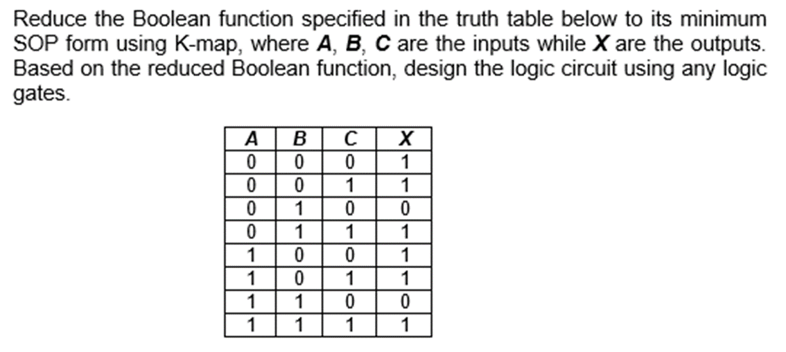

Transcribed Image Text:Reduce the Boolean function specified in the truth table below to its minimum
SOP form using K-map, where A, B, C are the inputs while X are the outputs.
Based on the reduced Boolean function, design the logic circuit using any logic
gates.
A
0
0
0
0
1
1
1
1
B
0
0
1
1
0
1
с
0
1
0
1
0
1
0
1
X
1
1
0
1
1
1
0
1

Transcribed Image Text:b) Refer to Figure Q2b. In a simple copy machine, a stop signal, S, is to be generated to
stop the machine operation and energize an indicator light whenever either of the following
conditions exists:
There is no paper in the paper feeder tray;
Or the TWO (2) microswitches in the paper path are activated, indicating a jam in
the paper path. The presence of paper in the feeder tray is indicated by a HIGH
at logic signal P.
Each of the microswitches produces a logic signal (Q and R) that goes HIGH whenever
paper is passing over the switch to activate it. Design the logic circuit to produce a HIGH
at output signal S for the stated conditions, and implement it using logic gates.
Paper sensing
switches
5V
Feeder Tray
Sensor
sw1
sw2
www
1 ΚΩ
1 ΚΩ
Figure Q2b
Q
R
P
Logic
Circuit
S
Expert Solution
This question has been solved!
Explore an expertly crafted, step-by-step solution for a thorough understanding of key concepts.

Step by stepSolved in 4 steps with 6 images

Knowledge Booster


Learn more about
Need a deep-dive on the concept behind this application? Look no further. Learn more about this topic, electrical-engineering and related others by exploring similar questions and additional content below.Similar questions
- 1. Design a 8 - to - 1 multiplexer using 2- to-1 multiplexer using blocks. 2. Using K- Map, simplify the following Boolean expression : Ү-2 (0, 2, 4, 6, 8, 10, 11, 12, 13) 3. Build the logic circuit for the following function using Programmable Read Only Memory. F1 = ĀBC + ABC + ABC + ABC F2 = ABC + ABC + ABC + ABC E (Ctrl)arrow_forwardCreate Truth table and logic diagram using basic gates F = X +YZarrow_forwardDesign a combinational logic circuit which has one output Z and a 4-bit input ABCD representing a binary number. Z should be 1 iff the input is at least 5, but is no greater than 11. Use one OR gate (three inputs) and three AND gates (with no more than three inputs each.)arrow_forward
- Fill in the truth table for the digital combinational logic circuit shown above. Show the "truth table" for each type of gate used as a way of indicating how you arrived at your solution. A B D E 1 1 1 1 1 1 1 1 1 1 1 1arrow_forwardHi, can you please help me with all these questions. Thank youarrow_forward6. For the logic circuit below complete the truth table. A B D 0. 1 1 7. The output of a two input OR gate is zero, only when (a) its both inputs are one (b) its either input : is zero (c) its both inputs are zero (d) its either input is zeroarrow_forward
arrow_back_ios
arrow_forward_ios
Recommended textbooks for you
- Introductory Circuit Analysis (13th Edition)Electrical EngineeringISBN:9780133923605Author:Robert L. BoylestadPublisher:PEARSON
 Delmar's Standard Textbook Of ElectricityElectrical EngineeringISBN:9781337900348Author:Stephen L. HermanPublisher:Cengage Learning
 Programmable Logic ControllersElectrical EngineeringISBN:9780073373843Author:Frank D. PetruzellaPublisher:McGraw-Hill Education
  Fundamentals of Electric CircuitsElectrical EngineeringISBN:9780078028229Author:Charles K Alexander, Matthew SadikuPublisher:McGraw-Hill Education
 Electric Circuits. (11th Edition)Electrical EngineeringISBN:9780134746968Author:James W. Nilsson, Susan RiedelPublisher:PEARSON
 Engineering ElectromagneticsElectrical EngineeringISBN:9780078028151Author:Hayt, William H. (william Hart), Jr, BUCK, John A.Publisher:Mcgraw-hill Education,
Introductory Circuit Analysis (13th Edition)
Electrical Engineering
ISBN:9780133923605
Author:Robert L. Boylestad
Publisher:PEARSON
Delmar's Standard Textbook Of Electricity
Electrical Engineering
ISBN:9781337900348
Author:Stephen L. Herman
Publisher:Cengage Learning
Programmable Logic Controllers
Electrical Engineering
ISBN:9780073373843
Author:Frank D. Petruzella
Publisher:McGraw-Hill Education
Fundamentals of Electric Circuits
Electrical Engineering
ISBN:9780078028229
Author:Charles K Alexander, Matthew Sadiku
Publisher:McGraw-Hill Education
Electric Circuits. (11th Edition)
Electrical Engineering
ISBN:9780134746968
Author:James W. Nilsson, Susan Riedel
Publisher:PEARSON
Engineering Electromagnetics
Electrical Engineering
ISBN:9780078028151
Author:Hayt, William H. (william Hart), Jr, BUCK, John A.
Publisher:Mcgraw-hill Education,