
Introductory Circuit Analysis (13th Edition)
13th Edition
ISBN: 9780133923605
Author: Robert L. Boylestad
Publisher: PEARSON
expand_more
expand_more
format_list_bulleted
Related questions
Question
how to solve this?
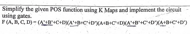

Transcribed Image Text:Simplify the given POS function using K Maps and implement the circuit
using gates.
F (A, B, C, D)
(A'+B'+C+D)(A+B+C+D')(A+B+C+D)(A+B+C+D')(A+B+C+D')
Expert Solution
This question has been solved!
Explore an expertly crafted, step-by-step solution for a thorough understanding of key concepts.

Step by stepSolved in 2 steps with 1 images

Knowledge Booster

Similar questions
- What logic function is performed by this circuit? VDD a. O d. e. A b. None OC AB AB A+B A+B O f. B AB M₁ M₂ M3 M4 F M5arrow_forwardUsing any design approach, plan and design the following problem: (show the Block Diagram, Truth Table, Simplification Approach Solution, Circuit Diagram) 2. Simple Security System A simple security system for two doors consists of a card reader and a keypad. Cand Reader To Door To Dor 2 To Alam Logic Circuit D E Keypad A person may open a particular door if he or she has a card containing the corresponding code and enters an authorized keypad code for that card. The outputs from the card reader are as follows: A B No card inserted Valid code for door 1 0 1 0 0 Valid code for door 2 1 1 Invalid card code 10 To unlock a door, a person must hold down the proper keys on the keypad and, then, insert the card in the reader. The authorized keypad codes for door 1 are 101 and 110, and the authorized keypad codes for door 2 are 101 and 011. If the card has an invalid code or if the wrong keypad code is entered, the alarm will ring when the card is inserted. If the correct keypad code is…arrow_forwardWhat is the final full formula? Minterm- F=C’D+A’B’D+ABD Maxterm- F=(C+D’)(A+B+D’)(A’+B’+D’) Draw the logic circuit:arrow_forward
- 5. Assume d3d₂d₁do is a BCD number and derive Boolean expression for segments b,c,e,f,g in a seven segment display in terms of d3d₂d₁do g 4 d Based on your boolean expressions derive the values of b,c,e,f,g segments when i. d3d₂d₁do= (0100) 2 ii. d3d₂d₁do = (0111)₂ iii. d3d2d₁do (1000)2arrow_forwardI was able to fill out the truth table for part A. I ONLY need help for PART B. B) Implement the logic function (z) using the multiplexer 74HC151 shows in the picture.arrow_forward1. Consider the following two logic circuits. VDD A-6 B-d6 A-6 B-6 -6 -6 F VDD F t t A Circuit A Circuit B a. Do these two circuits implement the same logic function? If yes, what is that logic function? If no, give Boolean expressions for both circuits. b. Will these two circuits' output resistances always be equal to each other? c. Will these two circuits' rise and fall times always be equal to each other? Why or why not?arrow_forward
- Could you please draw the logic diagram with gates for the equation in the photo, please? Thank you.arrow_forward9. The correct Boolean equation for the combination logic gate circuit sh B- c- a. Y=(A+B+ C ) D b. Y=(A+B) (C+D) c. Y (AB+C) d. Y=( ABC )D 0. The correct Boolean equation for the combination logic gate shown A - B-arrow_forwardQuestion 4: For the number display below, we would like to identify Boolean expression for LEDS (outputs a through g2) that indicate numbers 11, 14, and 15. a. Please write the Boolean expressions for the two LEDS (outputs a through g2) based on the input signals So to S3. You do not need to simplify the Boolean expressions. b. Please draw the logit circuit for outputs a through g2 a2 Logic circuit 2. 88 5,5,5,50arrow_forward
- Determine the logic expression for the output Y as a function of the inputsarrow_forward2-17 Draw the logic diagram corresponding to the following Boolean expressions without sim- plifying them: (a) BC' + AB + ACD (b) (A + B)(C + D)(A' + B + D) (c) (AB + A'B')(CD' + C'D)arrow_forward• Draw a logic circuit for (A + B)C. Draw a logic circuit for A + BC + D. • Draw a logic circuit for AB + AC. Draw a logic circuit for (A + B)(C+ D)C.arrow_forward
arrow_back_ios
SEE MORE QUESTIONS
arrow_forward_ios
Recommended textbooks for you
- Introductory Circuit Analysis (13th Edition)Electrical EngineeringISBN:9780133923605Author:Robert L. BoylestadPublisher:PEARSON
 Delmar's Standard Textbook Of ElectricityElectrical EngineeringISBN:9781337900348Author:Stephen L. HermanPublisher:Cengage Learning
 Programmable Logic ControllersElectrical EngineeringISBN:9780073373843Author:Frank D. PetruzellaPublisher:McGraw-Hill Education
  Fundamentals of Electric CircuitsElectrical EngineeringISBN:9780078028229Author:Charles K Alexander, Matthew SadikuPublisher:McGraw-Hill Education
 Electric Circuits. (11th Edition)Electrical EngineeringISBN:9780134746968Author:James W. Nilsson, Susan RiedelPublisher:PEARSON
 Engineering ElectromagneticsElectrical EngineeringISBN:9780078028151Author:Hayt, William H. (william Hart), Jr, BUCK, John A.Publisher:Mcgraw-hill Education,
Introductory Circuit Analysis (13th Edition)
Electrical Engineering
ISBN:9780133923605
Author:Robert L. Boylestad
Publisher:PEARSON
Delmar's Standard Textbook Of Electricity
Electrical Engineering
ISBN:9781337900348
Author:Stephen L. Herman
Publisher:Cengage Learning
Programmable Logic Controllers
Electrical Engineering
ISBN:9780073373843
Author:Frank D. Petruzella
Publisher:McGraw-Hill Education
Fundamentals of Electric Circuits
Electrical Engineering
ISBN:9780078028229
Author:Charles K Alexander, Matthew Sadiku
Publisher:McGraw-Hill Education
Electric Circuits. (11th Edition)
Electrical Engineering
ISBN:9780134746968
Author:James W. Nilsson, Susan Riedel
Publisher:PEARSON
Engineering Electromagnetics
Electrical Engineering
ISBN:9780078028151
Author:Hayt, William H. (william Hart), Jr, BUCK, John A.
Publisher:Mcgraw-hill Education,