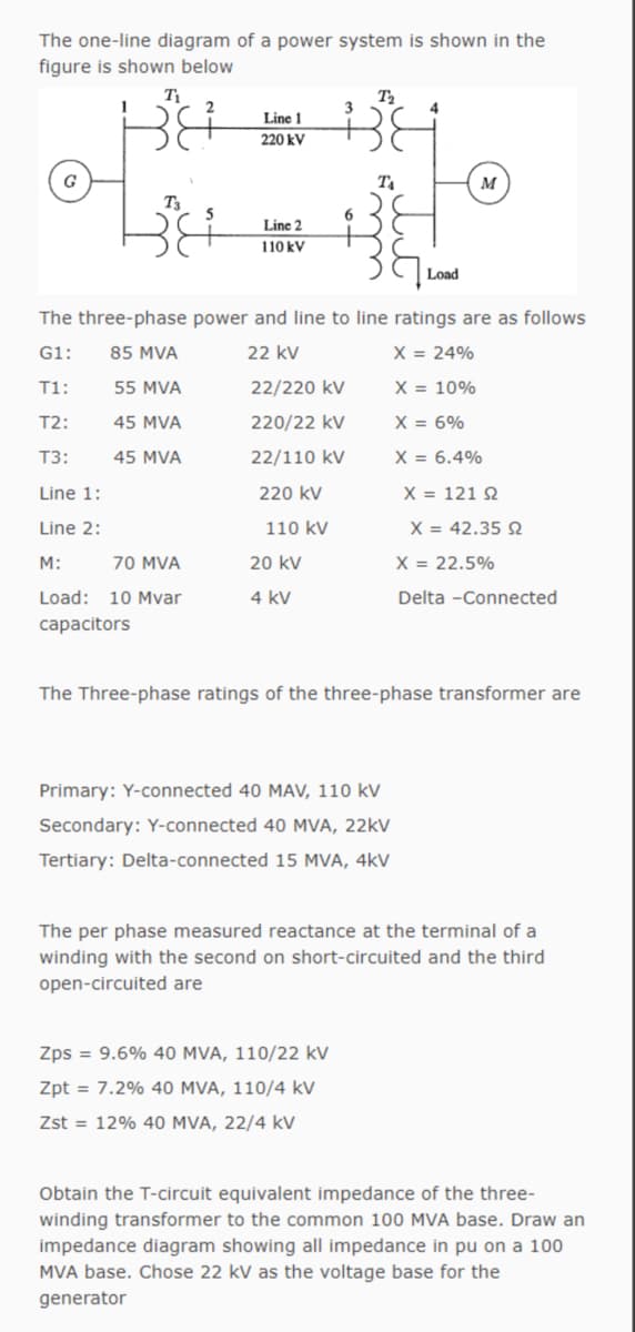
The one-line diagram of a power system is shown in the figure is shown below T Line 1 220 kV G M Line 2 110 kV Load The three-phase power and line to line ratings are as follows G1: 85 MVA 22 kV X = 24% T1: 55 MVA 22/220 kV X = 10% T2: 45 MVA 220/22 kV X = 6% T3: 45 MVA 22/110 kV X = 6.4% Line 1: 220 kV X = 121 2 Line 2: 110 kV X = 42.35 2 M: 70 MVA 20 kV X = 22.5% Load: 10 Mvar 4 kV Delta -Connected capacitors The Three-phase ratings of the three-phase transformer are Primary: Y-connected 40 MAV, 110 kV Secondary: Y-connected 40 MVA, 22kV Tertiary: Delta-connected 15 MVA, 4kV The per phase measured reactance at the terminal of a winding with the second on short-circuited and the third open-circuited are Zps = 9.6% 40 MVA, 110/22 kV Zpt = 7.2% 40 MVA, 110/4 kV Zst = 12% 40 MVA, 22/4 kV Obtain the T-circuit equivalent impedance of the three- winding transformer to the common 100 MVA base. Draw an impedance diagram showing all impedance in pu on a 100 MVA base. Chose 22 kV as the voltage base for the generator
The one-line diagram of a power system is shown in the figure is shown below T Line 1 220 kV G M Line 2 110 kV Load The three-phase power and line to line ratings are as follows G1: 85 MVA 22 kV X = 24% T1: 55 MVA 22/220 kV X = 10% T2: 45 MVA 220/22 kV X = 6% T3: 45 MVA 22/110 kV X = 6.4% Line 1: 220 kV X = 121 2 Line 2: 110 kV X = 42.35 2 M: 70 MVA 20 kV X = 22.5% Load: 10 Mvar 4 kV Delta -Connected capacitors The Three-phase ratings of the three-phase transformer are Primary: Y-connected 40 MAV, 110 kV Secondary: Y-connected 40 MVA, 22kV Tertiary: Delta-connected 15 MVA, 4kV The per phase measured reactance at the terminal of a winding with the second on short-circuited and the third open-circuited are Zps = 9.6% 40 MVA, 110/22 kV Zpt = 7.2% 40 MVA, 110/4 kV Zst = 12% 40 MVA, 22/4 kV Obtain the T-circuit equivalent impedance of the three- winding transformer to the common 100 MVA base. Draw an impedance diagram showing all impedance in pu on a 100 MVA base. Chose 22 kV as the voltage base for the generator

Power System Analysis and Design (MindTap Course List)
6th Edition
ISBN:9781305632134
Author:J. Duncan Glover, Thomas Overbye, Mulukutla S. Sarma
Publisher:J. Duncan Glover, Thomas Overbye, Mulukutla S. Sarma
Chapter3: Power Transformers
Section: Chapter Questions
Problem 3.23P: Figure 3.32 shows the oneline diagram of a three-phase power system. By selecting a common base of...

Related questions
Question
Please solve with steps
Transcribed Image Text:The one-line diagram of a power system is shown in the
figure is shown below
T
Line 1
220 kV
G
T
м
T3
6.
Line 2
110 kV
Load
The three-phase power and line to line ratings are as follows
G1:
85 MVA
22 kV
X = 24%
T1:
55 MVA
22/220 kV
X = 10%
T2:
45 MVA
220/22 kV
X = 6%
T3:
45 MVA
22/110 kV
X = 6.4%
Line 1:
220 kV
X = 121 2
Line 2:
110 kV
X = 42.35 N
M:
70 MVA
20 kV
X = 22.5%
Load: 10 Mvar
4 kV
Delta -Connected
capacitors
The Three-phase ratings of the three-phase transformer are
Primary: Y-connected 40 MAV, 110 kV
Secondary: Y-connected 40 MVA, 22KV
Tertiary: Delta-connected 15 MVA, 4kV
The per phase measured reactance at the terminal of a
winding with the second on short-circuited and the third
open-circuited are
Zps = 9.6% 40 MVA, 110/22 kV
Zpt = 7.2% 40 MVA, 110/4 kV
Zst = 12% 40 MVA, 22/4 kV
Obtain the T-circuit equivalent impedance of the three-
winding transformer to the common 100 MVA base. Draw an
impedance diagram showing all impedance in pu on a 100
MVA base. Chose 22 kV as the voltage base for the
generator
Expert Solution
This question has been solved!
Explore an expertly crafted, step-by-step solution for a thorough understanding of key concepts.

This is a popular solution!

Trending now
This is a popular solution!

Step by step
Solved in 6 steps with 8 images

Knowledge Booster


Learn more about
Need a deep-dive on the concept behind this application? Look no further. Learn more about this topic, electrical-engineering and related others by exploring similar questions and additional content below.Recommended textbooks for you
Power System Analysis and Design (MindTap Course …
Electrical Engineering
ISBN:
9781305632134
Author:
J. Duncan Glover, Thomas Overbye, Mulukutla S. Sarma
Publisher:
Cengage Learning

Delmar's Standard Textbook Of Electricity
Electrical Engineering
ISBN:
9781337900348
Author:
Stephen L. Herman
Publisher:
Cengage Learning
Power System Analysis and Design (MindTap Course …
Electrical Engineering
ISBN:
9781305632134
Author:
J. Duncan Glover, Thomas Overbye, Mulukutla S. Sarma
Publisher:
Cengage Learning
Delmar's Standard Textbook Of Electricity
Electrical Engineering
ISBN:
9781337900348
Author:
Stephen L. Herman
Publisher:
Cengage Learning