The rod is supported by smooth journal bearings at A, B, and C and is subjected to the two forces F =310 N and F2 = 540 N . (Figure 1) %3D A BF F, D 0.6 m 0.6 m 0.6 m 0.4 m
The rod is supported by smooth journal bearings at A, B, and C and is subjected to the two forces F =310 N and F2 = 540 N . (Figure 1) %3D A BF F, D 0.6 m 0.6 m 0.6 m 0.4 m

Mechanics of Materials (MindTap Course List)
9th Edition
ISBN:9781337093347
Author:Barry J. Goodno, James M. Gere
Publisher:Barry J. Goodno, James M. Gere
Chapter11: Columns
Section: Chapter Questions
Problem 11.2.4P: Repeat Problem 11.2-3 assuming that R= 10 kN · m/rad and L = 2 m.

Related questions
Question
100%
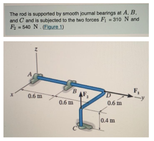
Transcribed Image Text:The rod is supported by smooth journal bearings at A, B,
and C and is subjected to the two forces F = 310 N and
F2 = 540 N . (Figure 1)
%3D
A
F,
AF
D
0.6 m
0.6 m
0.6 m
0.4 m
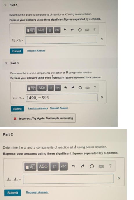
Transcribed Image Text:Part A
Determine the z and y components of reaction at C using scalar notation.
Express your answers using three significant figures separated by a comma.
AZO 1 vec
C..C, -
Submit
Request Answer
• Part B
Determine the z and z components of reaction at B using scalar notation.
Express your answers using three dignificant figures separated by a comma.
V AE vec
?
B.. B, = 1490, – 993
Submit
Previous Answers Request Answer
x Incorrect; Try Again; 5 attempts remaining
Part C
Determine the z and z components of reaction at A using scalar notation.
Express your answers using three significant figures separated by a comma.
VAE vec
Az, A =
N
Submit
Request Answer
Expert Solution
This question has been solved!
Explore an expertly crafted, step-by-step solution for a thorough understanding of key concepts.

Step by step
Solved in 2 steps with 2 images

Recommended textbooks for you
Mechanics of Materials (MindTap Course List)
Mechanical Engineering
ISBN:
9781337093347
Author:
Barry J. Goodno, James M. Gere
Publisher:
Cengage Learning
Mechanics of Materials (MindTap Course List)
Mechanical Engineering
ISBN:
9781337093347
Author:
Barry J. Goodno, James M. Gere
Publisher:
Cengage Learning