
Structural Analysis
6th Edition
ISBN: 9781337630931
Author: KASSIMALI, Aslam.
Publisher: Cengage,
expand_more
expand_more
format_list_bulleted
Related questions
Concept explainers
Question
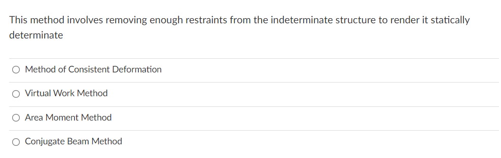

Transcribed Image Text:This method involves removing enough restraints from the indeterminate structure to render it statically
determinate
O Method of Consistent Deformation
O Virtual Work Method
O Area Moment Method
Conjugate Beam Method
Expert Solution
This question has been solved!
Explore an expertly crafted, step-by-step solution for a thorough understanding of key concepts.

Step by stepSolved in 3 steps

Knowledge Booster


Learn more about
Need a deep-dive on the concept behind this application? Look no further. Learn more about this topic, civil-engineering and related others by exploring similar questions and additional content below.Similar questions
- Given the assumptions made in thin plate bending theory are already known,take a rectangular four-node thin plate bending element as an example and discuss compatibility of the element. (A diagram would be very useful) thanksarrow_forwardQuestion 2 In the below structure, the truss members stiffness matrix has been used for truss members and the beam stiffness matrix has been used for the rest. a) How many unknown displacements are in the displacement vector? b) How many displacements are in the displacement vector altogether? * J Aarrow_forwardAn element is subject to the following normal and shear strains: Ex = -350 × 10-6 €y = 200 x 10-6 Yxy = 300 X 10-6 If the element were oriented at an angle of 15° counterclockwise: a) Determine the normal and shear strains €¸', €', and Yx'y'. b) The principal strains and the orientation upon which they act. c) The maximum in-plane shear strain and the orientation upon which they act.arrow_forward
- Part 2,3,4arrow_forwardShow the relationship between axial stress and strain to get the axial deformationarrow_forwardNOTE: 1. The following are grounds for not considering your solution and final answers: a)Figures not properly labeled. b)Equations that are not consistent with the firgure. C)Equilibrium equations do not have sign conventions. d) unsequenced solution. e) answers without units 2. Computations accurate to the nearest tenths. Problem. Show that the following structures are statically determinate and determine the support reactions. b) B is pin connected, C is fixed, hinge supports A and D. 8 kN 8 kN 2 m -2 m 3 kN/m C 4 m D -3 marrow_forward
- Why should the loading be linearly related to the stress or Displacement that is to be determined?arrow_forwardI need help with this exercise from my homework. I have no idea about how to solve it. I need an step by step solving and explanation, please.arrow_forwardElementary beam theory predicts that the axial bending stress ox in a prismatic beam is given by: ox = (M.I,M,L)y+(M,I.-M.I.) (1,1₂-13/2) where My and M₂ are bending moments applied to a cross-section, and where ly, lz and lyz are second moments of area in the usual notation (Oxyz is a Cartesian coordinate system in which the x axis corresponds to the centroidal axis of the beam). (iii) A Z--section beam has the cross-section shown overleaf (see Figure QB2). The second moments of area of the section about the y and z axes are given as;; ly = 1.12x106mm² and I₂ = 2.87x106 mm4. Show that lyz = 1.35x106 mm² (use the parallel axis theorem). 100 60 10 y -10 10 60 Figure QB2 N (iv) Bending moments Mz = 2.0 kNm and My = 0 kNm act on a cross- -section of the beam of part (iii). Obtain an expression for the bending stress and sketch the orientation of the neutral axis with reference to the y and z axes. What is the maximum tensile value of the axial bending stress and where does it occur?arrow_forward
- The figure shows a beam made from a material having an allowable tensile stress of 135 MPa and a compressive stress of 165 MPa. The couple M is applied to the beam in a plane forming an angle of 45° as shown in the figure. a) Determine the location of the centroid of the cross section b) Calculate the moments of inertia about the principal axes, I, and ly c) Determine the maximum allowable internal moment M that can be applied to the beam N M Y 140 mm 140 mm 45⁰ 140 mm 280 mm 140 mm 140 mmarrow_forwardPlease provide solution for this queryarrow_forwardWrite the number of elements, nodes required and degree of freedom to solve following truss using FEM (Use the best node/element numbering; Do not need to solve it!) Would ANSYS be able to solve the structure with given Boundary Conditions (BC)? If not, what should be done and why?arrow_forward
arrow_back_ios
SEE MORE QUESTIONS
arrow_forward_ios
Recommended textbooks for you
 Structural Analysis (10th Edition)Civil EngineeringISBN:9780134610672Author:Russell C. HibbelerPublisher:PEARSON
 Principles of Foundation Engineering (MindTap Cou...Civil EngineeringISBN:9781337705028Author:Braja M. Das, Nagaratnam SivakuganPublisher:Cengage Learning
 Fundamentals of Structural AnalysisCivil EngineeringISBN:9780073398006Author:Kenneth M. Leet Emeritus, Chia-Ming Uang, Joel LanningPublisher:McGraw-Hill Education
 Traffic and Highway EngineeringCivil EngineeringISBN:9781305156241Author:Garber, Nicholas J.Publisher:Cengage Learning
Structural Analysis (10th Edition)
Civil Engineering
ISBN:9780134610672
Author:Russell C. Hibbeler
Publisher:PEARSON
Principles of Foundation Engineering (MindTap Cou...
Civil Engineering
ISBN:9781337705028
Author:Braja M. Das, Nagaratnam Sivakugan
Publisher:Cengage Learning
Fundamentals of Structural Analysis
Civil Engineering
ISBN:9780073398006
Author:Kenneth M. Leet Emeritus, Chia-Ming Uang, Joel Lanning
Publisher:McGraw-Hill Education
Traffic and Highway Engineering
Civil Engineering
ISBN:9781305156241
Author:Garber, Nicholas J.
Publisher:Cengage Learning