VR Line impedance Mi M1 Transformer Vs VT M3 M: M2 Line impedance neutral Line impedance M3 Figure 2: Distribution lines equivalent circuit. Figure 1: Low voltage lines exiting the distribution transformer center. In the given circuit, low voltage lines are seen coming out of a distribution transformer whose Low Voltage side is star connected. R (R = 0) phase for M1 line, S (@S = 120) phase for M2 line andT (øT = -120) phase is used for M3 line. The impedances of the loads at the end of the lines are (100 + j25) N and the impedances of the lines (1 + j) N. • Find line currents
VR Line impedance Mi M1 Transformer Vs VT M3 M: M2 Line impedance neutral Line impedance M3 Figure 2: Distribution lines equivalent circuit. Figure 1: Low voltage lines exiting the distribution transformer center. In the given circuit, low voltage lines are seen coming out of a distribution transformer whose Low Voltage side is star connected. R (R = 0) phase for M1 line, S (@S = 120) phase for M2 line andT (øT = -120) phase is used for M3 line. The impedances of the loads at the end of the lines are (100 + j25) N and the impedances of the lines (1 + j) N. • Find line currents

Power System Analysis and Design (MindTap Course List)
6th Edition
ISBN:9781305632134
Author:J. Duncan Glover, Thomas Overbye, Mulukutla S. Sarma
Publisher:J. Duncan Glover, Thomas Overbye, Mulukutla S. Sarma
Chapter3: Power Transformers
Section: Chapter Questions
Problem 3.41P: Consider the single-line diagram of the power system shown in Figure 3.38. Equipment ratings are...

Related questions

Question
Transcribed Image Text:Line impedance
Mi
M1
Transformer,
Vs
VT
M3,
M:
М2
Line impedance
neutral
Line impedance
M3
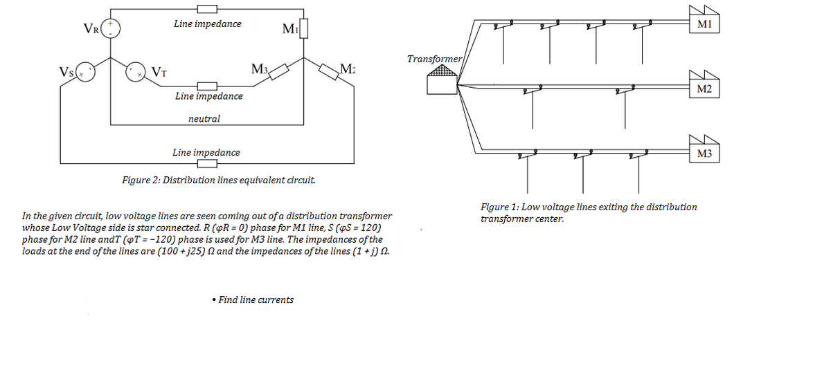
Figure 2: Distribution lines equivalent circuit.
Figure 1: Low voltage lines exiting the distribution
transformer center.
In the given circuit, low voltage lines are seen coming out of a distribution transformer
whose Low Voltage side is star connected. R (OR = 0) phase for M1 line, S (pS = 120)
phase for M2 line andT (oT = -120) phase is used for M3 line. The impedances of the
loads at the end of the lines are (100 + j25) N and the impedances of the lines (1 + j) N.
• Find line currents
Expert Solution
This question has been solved!
Explore an expertly crafted, step-by-step solution for a thorough understanding of key concepts.

Step by step
Solved in 2 steps with 2 images

Knowledge Booster


Learn more about
Need a deep-dive on the concept behind this application? Look no further. Learn more about this topic, electrical-engineering and related others by exploring similar questions and additional content below.Recommended textbooks for you
Power System Analysis and Design (MindTap Course …
Electrical Engineering
ISBN:
9781305632134
Author:
J. Duncan Glover, Thomas Overbye, Mulukutla S. Sarma
Publisher:
Cengage Learning
Power System Analysis and Design (MindTap Course …
Electrical Engineering
ISBN:
9781305632134
Author:
J. Duncan Glover, Thomas Overbye, Mulukutla S. Sarma
Publisher:
Cengage Learning