// State true or false 1. The line currents drawn by a A connected load has no zero sequence components. 2. The relation between the line to line voltage and line to neutral voltage in a three phase system is VL = v2 V-N %3D 3. The positive sequence of a transformer is equal to 3 times its negative sequence reactance.
// State true or false 1. The line currents drawn by a A connected load has no zero sequence components. 2. The relation between the line to line voltage and line to neutral voltage in a three phase system is VL = v2 V-N %3D 3. The positive sequence of a transformer is equal to 3 times its negative sequence reactance.

Power System Analysis and Design (MindTap Course List)
6th Edition
ISBN:9781305632134
Author:J. Duncan Glover, Thomas Overbye, Mulukutla S. Sarma
Publisher:J. Duncan Glover, Thomas Overbye, Mulukutla S. Sarma
Chapter3: Power Transformers
Section: Chapter Questions
Problem 3.37P: Three single-phase two-winding transformers, each rated 25MVA,54.2/5.42kV, are connected to form a...

Related questions

Question
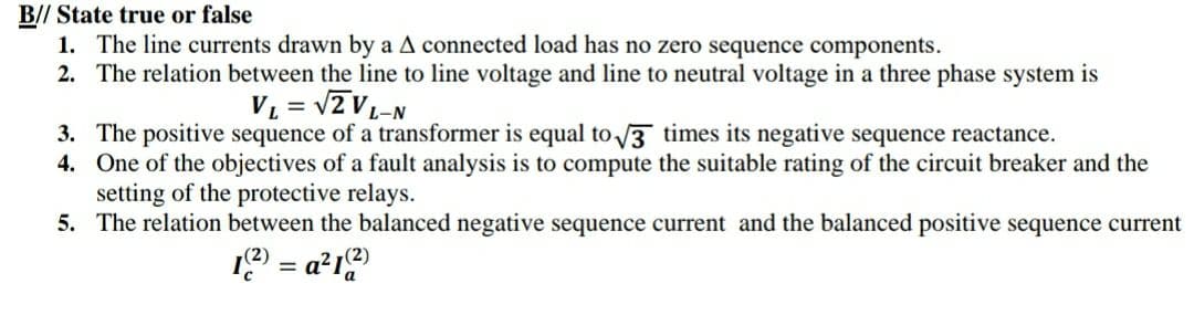
Transcribed Image Text:B// State true or false
1. The line currents drawn by a A connected load has no zero sequence components.
2. The relation between the line to line voltage and line to neutral voltage in a three phase system is
VL = v2 V-N
3. The positive sequence of a transformer is equal to 3 times its negative sequence reactance.
4. One of the objectives of a fault analysis is to compute the suitable rating of the circuit breaker and the
setting of the protective relays.
5. The relation between the balanced negative sequence current and the balanced positive sequence current
19 = a²19
Expert Solution
This question has been solved!
Explore an expertly crafted, step-by-step solution for a thorough understanding of key concepts.

Step by step
Solved in 4 steps with 1 images

Knowledge Booster


Learn more about
Need a deep-dive on the concept behind this application? Look no further. Learn more about this topic, electrical-engineering and related others by exploring similar questions and additional content below.Recommended textbooks for you
Power System Analysis and Design (MindTap Course …
Electrical Engineering
ISBN:
9781305632134
Author:
J. Duncan Glover, Thomas Overbye, Mulukutla S. Sarma
Publisher:
Cengage Learning
Power System Analysis and Design (MindTap Course …
Electrical Engineering
ISBN:
9781305632134
Author:
J. Duncan Glover, Thomas Overbye, Mulukutla S. Sarma
Publisher:
Cengage Learning