Electrical Engineering: Principles & Applications, 7th Edition
7th Edition
ISBN: 9780134485201
Author: Allan R. Hambley
Publisher: PEARSON
expand_more
expand_more
format_list_bulleted
Videos
Textbook Question
Chapter 1, Problem 1.37P
Use KCL to find the values of
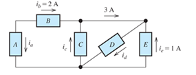
Figure P1.37
Expert Solution & Answer

Learn your wayIncludes step-by-step video

schedule05:04
Students have asked these similar questions
Use KCL to find the values of i a, i c, and i d for the circuit of Figure P1.37. Which elements are connected in series in this circuit?
Subject: Circuits 1
What voltage will be required to produce a flow of 15A, through a resistance of 12 ohms?
3. Given:
VS1: 18 voltsVS2: -1 voltsRB1: 1000 ohmsRB2: 6500 ohmsRB3: 8000 ohmsRB4: 5000 ohmsB=beta: 75RE: 540 ohmsVE: ? volts
Chapter 1 Solutions
Electrical Engineering: Principles & Applications, 7th Edition
Ch. 1 - Broadly speaking, what are the two main objectives...Ch. 1 - Prob. 1.2PCh. 1 - List eight subdivisions of electrical engineering.Ch. 1 - Prob. 1.4PCh. 1 - Prob. 1.5PCh. 1 - In the fluid-flow analogy for electrical circuits,...Ch. 1 - The charge of an electron is 1.601019C . A current...Ch. 1 - The ends of a length of wire are labeled a and b....Ch. 1 - The circuit element shown in Figure P1.9 has v=12V...Ch. 1 - Prob. 1.10P
Ch. 1 - The net charge through a cross section of a...Ch. 1 - The current through a particular circuit element...Ch. 1 - The current through a given circuit element is...Ch. 1 - The net charge through a cross section of a...Ch. 1 - A copper wire has a diameter of 2.05 mm and...Ch. 1 - A certain lead acid storage battery has a mass of...Ch. 1 - A circuit element having terminals a and b has...Ch. 1 - An electron moves through a voltage of 9 V from...Ch. 1 - A typical “deep-cycle” battery (used for electric...Ch. 1 - Define the term passive reference configuration....Ch. 1 - Compute the power for each element shown in Figure...Ch. 1 - The terminals of an electrical device are labeled...Ch. 1 - The terminals of a certain battery are labeled a...Ch. 1 - The element shown in Figure P1.24 I has v(t)=10V...Ch. 1 - The current and voltage of an electrical device...Ch. 1 - Suppose that the cost of electrical energy is...Ch. 1 - Figure P1.27 shows an ammeter (AM) and voltmeter...Ch. 1 - Repeat Problem P1.27 with the meters connected as...Ch. 1 - A certain type of D-cell battery that costs $0.50...Ch. 1 - The electronics aboard a certain sailboat consume...Ch. 1 - What s a node in an electrical circuit? Identify...Ch. 1 - State Kirchhoff’s current law.Ch. 1 - Two electrical elements are connected in series....Ch. 1 - Suppose that in the fluid-flow analogy for an...Ch. 1 - Identify elements that are in series in the...Ch. 1 - Consider the circuit shown in Figure P1.36. Which...Ch. 1 - Use KCL to find the values of ia, ic , and id for...Ch. 1 - Find the values of the other currents in Figure...Ch. 1 - Prob. 1.39PCh. 1 - State Kirchhoff’s voltage law.Ch. 1 - Consider the circuit shown in Figure P1.36. Which...Ch. 1 - Use KVL to solve for the voltages va , vb, and vc...Ch. 1 - Solve for the other voltages shown in Figure P1.43...Ch. 1 - Use KVL and KCL to solve for the labeled currents...Ch. 1 - Identify elements that are in parallel in Figure...Ch. 1 - Points a, b, c, and d appear in a certain circuit....Ch. 1 - In your own words, define an ideal conductor; an...Ch. 1 - Name four types of dependent sources and give the...Ch. 1 - State Ohm’s law, including references.Ch. 1 - Draw a circuit that contains a 5 resistance, a...Ch. 1 - Repeat Problem P1.50, placing all three elements...Ch. 1 - The resistance of a certain copper wire is 0.5. ....Ch. 1 - Draw a circuit that contains a 5 resistor, a 10-V...Ch. 1 - Draw a circuit that contains a 5 resistor, a 10-V...Ch. 1 - A power of 100 W is delivered to a certain...Ch. 1 - The voltage across a 10 resistor is given by...Ch. 1 - The voltage across a 10 resistor is given by...Ch. 1 - A certain wire has a resistance of 0.5 . Find the...Ch. 1 - Plot i versus v to scale for each of the parts of...Ch. 1 - Which of the following are self-contradictory...Ch. 1 - Consider the circuit shown in Figure P1.61. Find...Ch. 1 - Consider the circuit shown in Figure P1.62. Find...Ch. 1 - Consider the circuit shown in Figure P1.63. Find...Ch. 1 - Consider the circuit shown in Figure P1.64. Use...Ch. 1 - Determine the value of Ix in the circuit shown in...Ch. 1 - Consider the circuit shown in Figure P1.66. Figure...Ch. 1 - Prob. 1.67PCh. 1 - Consider the circuit shown in Figure P1.68. Figure...Ch. 1 - Solve for the currents shown in Figure P1.69....Ch. 1 - The circuit shown in Figure P1.70 contains a...Ch. 1 - Determine the value of vx and iy in the circuit...Ch. 1 - A 10-V independent voltage source is in series...Ch. 1 - A 10-V independent voltage source is in parallel...Ch. 1 - Consider the circuit shown in Figure P1.74. Figure...Ch. 1 - The circuit shown in Figure P1.75 contains a...Ch. 1 - For the circuit shown in Figure P1.76, solve for...Ch. 1 - For the circuit shown in Figure P1.77, solve for...Ch. 1 - Match each entry in Table T1.1(a) with the best...Ch. 1 - Prob. 1.2PTCh. 1 - The circuit of Figure T1.3 has I1=3A , I2=1A ,...Ch. 1 - The circuit shown in Figure T1.4 has Vs=12V ,...Ch. 1 - We are given Vs=15V , R=10 , and =0.3S for the...Ch. 1 - We are given i4=2A for the circuit of Figure T1.6....
Additional Engineering Textbook Solutions
Find more solutions based on key concepts
The switch in the bottom loop of Fig. P6.1 is closed at t = 0 and then opened at a later time t1. What is the d...
Fundamentals of Applied Electromagnetics (7th Edition)
For the network of Fig. 8.118: Determine the current through the 12 resistor using branch-current analysis. Co...
Introductory Circuit Analysis (13th Edition)
Write a while loop that lets the user enter a number. The number should be multiplied by 10, and the result ass...
Starting Out with Python (3rd Edition)
Three 150 mm 300 mm concrete cylinders with water to cement ratios of 0.4, 0.6, and 0.8, respectively. After c...
Materials for Civil and Construction Engineers (4th Edition)
Write an expression that is a 1 only if all of its variables (A, 6, C, D, and E) are 1 s.
Digital Fundamentals (11th Edition)
If you want to store objects of a class that you have written as values in a map, what requirement must the cla...
Starting Out with C++ from Control Structures to Objects (9th Edition)
Knowledge Booster


Learn more about
Need a deep-dive on the concept behind this application? Look no further. Learn more about this topic, electrical-engineering and related others by exploring similar questions and additional content below.Similar questions
- For the circuit shown in Figure P1.77, solve for the current i x. What types of sources are present in this circuit?arrow_forwardFigure P1.27 shows an ammeter (AM) and voltmeter (VM) connected to measure thecurrent and voltage, respectively, for circuit element A. When current actually enters the + terminalof the ammeter, the reading is positive, and when current leaves the + terminalreading is negative. If the actual voltage polarity is positive at the + terminal of the VM, thereading is positive; otherwise, it is negative. (Actually, for the connection shown, the ammeterreads the sum of the current in element A and the very small current taken by the voltmeter. Forpurposes of this problem, assume that the current taken by the voltmeter is negligible.) Find thepower for element A and state whether energy is being delivered to element A or taken from it if a. the ammeter reading is +2 A and the voltmeter reading is +30 V.b. the ammeter reading is -2 A and the voltmeter reading is - 30 V.c. the ammeter reading is -2 A and the voltmeter reading is + 30 V.arrow_forwardThe voltage and power values for each of the elements shown in P1.30 are given in Table P1.30. Find the value of the current through each of the elements usingthe values of power and voltage and the current directions shown inthe figure.arrow_forward
- the current (in mA) in each resistor shown in the figure aboveIR1IR2IR3 the potential difference between points c and f (Give the magnitude of your answer in volts and select the point of highest potential.) magnitude of potential difference What If? If all of the resistors in the circuit were decreased in value by a factor of 1,000, would the current in each resistor simply increase by a factor of 1,000? Explain your answer.arrow_forward5a. What is E2=? 5b. What is E3=? 5c. What is the potential difference of b relative to point a (V_ba)?arrow_forwardCurrent is the flow of charges in a directed path. When we connect yourmobile phone charger to the sockets in your various homes, charges startflowing through. Describe into details where these charges are generatedfrom and the processes involved.arrow_forward
- Using Passive Sign Convention, plot P2v(t) the power for the 2V source acrossthe following time range -10s ≤ t ≤ 10slabel athe plotarrow_forwardThe resistance of a given device is 46ohms at 25degrees celcius. If the temperature coefficient of resistance of the material is 0.00454 at 20degrees celius, determine the temperature of the device when its resistance is 92ohms.arrow_forwardh. What is the dc power dissipated by the device at the operating point?i. What is the power supplied by VCC ?j. Determine the power dissipated by the resistive elements by taking the difference betweenthe results of parts (h) and (i).arrow_forward
- Ohm's law describes the relation of energy and power dissipated by an element. Select one: True Falsearrow_forwardDetermine the drop voltage in the resistance R1, when BT1 = 13.6 V and resistance R1 = 4.6 kΩ.arrow_forwardA) Find the equivalent resistor of the circle between points a and b?B) If a constant voltage source (15V) is placed between points a and b, calculate a valueCurrent iSarrow_forward
arrow_back_ios
SEE MORE QUESTIONS
arrow_forward_ios
Recommended textbooks for you
 Introductory Circuit Analysis (13th Edition)Electrical EngineeringISBN:9780133923605Author:Robert L. BoylestadPublisher:PEARSON
 Delmar's Standard Textbook Of ElectricityElectrical EngineeringISBN:9781337900348Author:Stephen L. HermanPublisher:Cengage Learning
 Programmable Logic ControllersElectrical EngineeringISBN:9780073373843Author:Frank D. PetruzellaPublisher:McGraw-Hill Education
 Fundamentals of Electric CircuitsElectrical EngineeringISBN:9780078028229Author:Charles K Alexander, Matthew SadikuPublisher:McGraw-Hill Education
 Electric Circuits. (11th Edition)Electrical EngineeringISBN:9780134746968Author:James W. Nilsson, Susan RiedelPublisher:PEARSON
 Engineering ElectromagneticsElectrical EngineeringISBN:9780078028151Author:Hayt, William H. (william Hart), Jr, BUCK, John A.Publisher:Mcgraw-hill Education,
Introductory Circuit Analysis (13th Edition)
Electrical Engineering
ISBN:9780133923605
Author:Robert L. Boylestad
Publisher:PEARSON
Delmar's Standard Textbook Of Electricity
Electrical Engineering
ISBN:9781337900348
Author:Stephen L. Herman
Publisher:Cengage Learning
Programmable Logic Controllers
Electrical Engineering
ISBN:9780073373843
Author:Frank D. Petruzella
Publisher:McGraw-Hill Education
Fundamentals of Electric Circuits
Electrical Engineering
ISBN:9780078028229
Author:Charles K Alexander, Matthew Sadiku
Publisher:McGraw-Hill Education
Electric Circuits. (11th Edition)
Electrical Engineering
ISBN:9780134746968
Author:James W. Nilsson, Susan Riedel
Publisher:PEARSON
Engineering Electromagnetics
Electrical Engineering
ISBN:9780078028151
Author:Hayt, William H. (william Hart), Jr, BUCK, John A.
Publisher:Mcgraw-hill Education,
Lesson 2 - Source Transformations, Part 2 (Engineering Circuits); Author: Math and Science;https://www.youtube.com/watch?v=7gno74RhVGQ;License: Standard Youtube License