
Concept explainers
Videos
The circuit shown in Figure T1.4 has
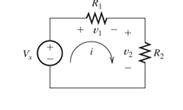
Figure T1.4
a. Find the values of: a.
Want to see the full answer?
Check out a sample textbook solution
Chapter 1 Solutions
Modified Masteringengineering With Pearson Etext -- Standalone Access Card -- For Electrical Engineering: Principles & Applications
Additional Engineering Textbook Solutions
Introductory Circuit Analysis (13th Edition)
Principles Of Electric Circuits
Programmable Logic Controllers
Engineering Electromagnetics
Basic Engineering Circuit Analysis
Fundamentals of Electric Circuits


- Helping tags: Electric Circuit Theory, Circuits, Electronics EngineeringHelp me answer the questions, the given is just the same. Will upvote, just pls show complete solutions and explain if necessary. Thanks!arrow_forwardFigure P1.27 shows an ammeter (AM) and voltmeter (VM) connected to measure thecurrent and voltage, respectively, for circuit element A. When current actually enters the + terminalof the ammeter, the reading is positive, and when current leaves the + terminalreading is negative. If the actual voltage polarity is positive at the + terminal of the VM, thereading is positive; otherwise, it is negative. (Actually, for the connection shown, the ammeterreads the sum of the current in element A and the very small current taken by the voltmeter. Forpurposes of this problem, assume that the current taken by the voltmeter is negligible.) Find thepower for element A and state whether energy is being delivered to element A or taken from it if a. the ammeter reading is +2 A and the voltmeter reading is +30 V.b. the ammeter reading is -2 A and the voltmeter reading is - 30 V.c. the ammeter reading is -2 A and the voltmeter reading is + 30 V.arrow_forwardThe element shown in Figure P1.24 has v(t) = 10 V and i(t) = 2 e-t A. Compute the power for the circuit element. Find the energy transferred between t = 0 and t = ∞. Is this energy absorbed by the element or supplied by it?arrow_forward
- The numerical values for the currents and voltages in the circuit inP1.29 are given in Table P1.29. Find the total power developed inthe circuit.arrow_forwardFor the question and solution provided, i do not understand why gain is = R2/ R1+R2. From the equation R2wc/ (R1+R2)wc +1 why do we ignore the +1? When omega = 0, H(0) = 0 when omega = infinity, H(infinity) = 1 shouldn't H(infinity) be equals 1 instead of 2/3 ?arrow_forwardDetermine the force-voltage and force-current analogy Where, K=1, fv1= 1, fv2= 3+b, fv3= 3/2, fv4= 3+c M1= 2+a, M2= 5 The value of a= 3, b=1, c=2arrow_forward
- Meaning of this method? m2t = α + bet-1 + dm2t-1+ f%Δ(Rt – rt) + goct + g1ct-1 + g2ct-2 + εtarrow_forward1. a. Find the equivalent resistance ??? in the circuit in Figure given below byusing a Y-to-∆ transformation involving resistors ?2, ?3, and ?5.b. Repeat (a) using a ∆-to-Y transformation involving resistors ?3, ?4and ?5arrow_forwardShow your complete solution. TY.arrow_forward
- Use KCL to find the values of i a, i c, and i d for the circuit of Figure P1.37. Which elements are connected in series in this circuit?arrow_forward1. Using delta to wye transformation, determine the wye equivalent circuit of the delta circuit formed by R1, R2, and R3. 7. Draw the transformed circuit in step 1 into a single resistance (REQ). Is this equal to the measured RT?arrow_forwardPlease answer the following points in detail and rigorously. Instead ofresort to formulas, develop from basic principles (laws ofvoltages and currents, definition of electrical power, properties ofphasors, among others) d) Show that the complex power consumed by two elements in parallel is the sum of the individual complex powers. After, repeat the procedure but for two elements in series. e) What meaning would you give to the P consumed by an element? Which to Q? f) Suppose you know P and Q for a two-terminal element. What is the power factor of this element? When would i be in early and when behind? g) Suppose you know the equivalent resistance R and the reactance X equivalent of a two-terminal passive network. What is the factor power of red bliss? When would I be in advance and when in backwardness?arrow_forward
 Introductory Circuit Analysis (13th Edition)Electrical EngineeringISBN:9780133923605Author:Robert L. BoylestadPublisher:PEARSON
 Delmar's Standard Textbook Of ElectricityElectrical EngineeringISBN:9781337900348Author:Stephen L. HermanPublisher:Cengage Learning
 Programmable Logic ControllersElectrical EngineeringISBN:9780073373843Author:Frank D. PetruzellaPublisher:McGraw-Hill Education
 Fundamentals of Electric CircuitsElectrical EngineeringISBN:9780078028229Author:Charles K Alexander, Matthew SadikuPublisher:McGraw-Hill Education
 Electric Circuits. (11th Edition)Electrical EngineeringISBN:9780134746968Author:James W. Nilsson, Susan RiedelPublisher:PEARSON
 Engineering ElectromagneticsElectrical EngineeringISBN:9780078028151Author:Hayt, William H. (william Hart), Jr, BUCK, John A.Publisher:Mcgraw-hill Education,