
Concept explainers
Videos
Figure Pl.5 shows the topology of a photo-voltaic (PV) system that uses solar cells to supply electrical power to a residence with hybrid electnc vehicle toads (Gurkavnak. 2009). The system consists of a PV array to collect the sun's rays, a battery pack to store energy during the day. a dc/ac inverter to supply ac power to the load, and a bidirectional dc/dc converter to control the terminal voltage of the solar array according to a maxunum power point tracking (MPPT) algorithm. In case of sufficient solar power (solar insolation), the dc/dc converter charges die battery and die solar array supplies power to the load through the dc/ac inverter. Widi less or no solar energy (solar non-insolation). power is supplied from the battery to the load through the dc/dc converter and die dc/ac inverter. Thus, the dc/dc converter must be bidirectional to be able to charge and discharge the batlery. With the MPPT controller providing the reference voltage, the converter operates as a step-up converter (boost) to discharge the battery if the battery is full or a step-down (buck) converter, which charges die batlery if it is not full.7
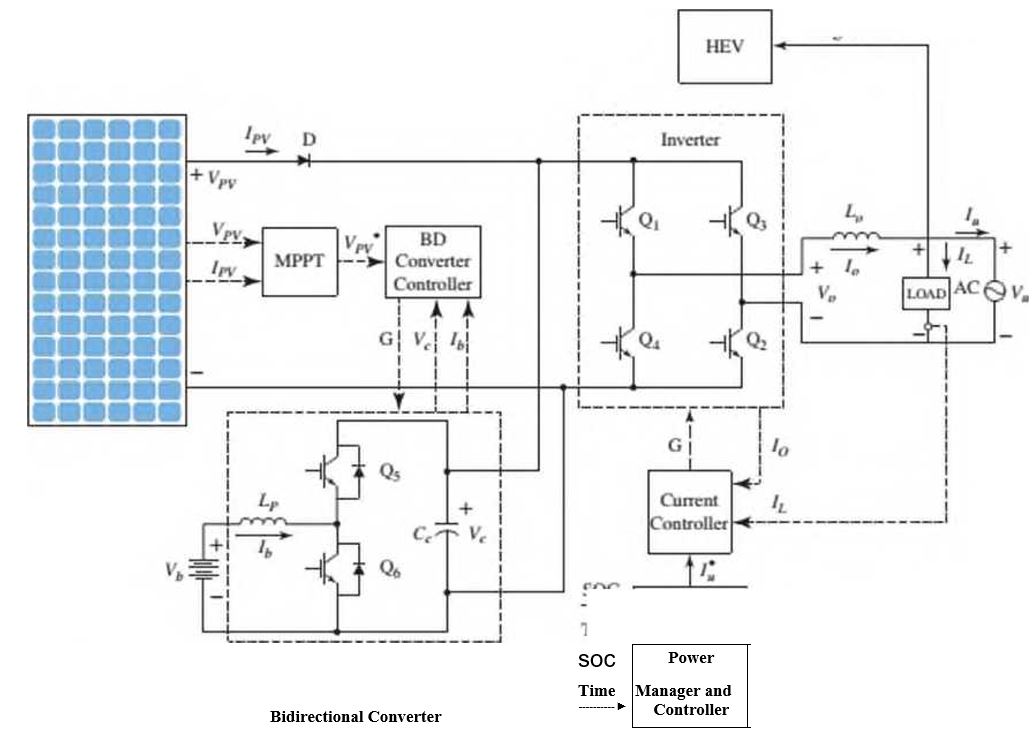
In Figure Pl.5, the Inverter is controlled by die Power Manager and Controller through the Current Controller. The Power Manager and Controller directs the Inverter to take power either from the battery, via the Bidirectional Converter, or the solar array.
of charge (SOC). Draw the follow ing two functional block diagrams for this system:
- A diagram that illustrates the conversion of solar irradiation into energy stored in the battery. In that diagram, the input is the solar irradiance. r(t), and the output is the battery voltage. Vb(t).
- The main diagram, in w hich the input is the desired output voltage. Vr(t) and the output is the actual inverter output voltage, Vo(t) Both of these functional block diagrams should show their major components, including the PV array, MPPT controller, dc/dc converter, battery pack, dc/ac inverter, current controller, and the Power Manager and Controller. Show all signals, including intermediate voltages and currents, time of day. and the SOC of the battery.
Want to see the full answer?
Check out a sample textbook solution
Chapter 1 Solutions
Control Systems Engineering 7e


- Geochemical Box Models - please use same terminology found in question Consider an element X exchanging between two geochemical reservoirs A and B. Let MA and MB be the masses of X in reservoirs A and B, respectively; let tA and tB be the residence times of X in reservoirs A and B, respectively. Further let M = MA + MB be the total mass of X in the two reservoirs combined. Consider a situation where additional mass M' is injected into reservoir A at time t=0 increasing the total amount of element X in the system from M0 to M1, with no further injection at later times; further assume that tA >> tB, that the total mass in the altered system is M1 = M0 + M', and that M0 << M'. Give an expression for MB(t) as a function of M1, tA, tB, and t. What is the characteristic time for MB to approach steady state? What is the characteristic time for MA to approach steady state?arrow_forwardYou are testing a long-dwelling catheter for its biological response using a rat model. After implantation for 4 months you explant the catheter material and surrounding tissue. Histology shows the catheter material surrounded by a thin layer of aligned collagen that is, in turn, surrounded by numerous polymorphonuclear cells. What has occurred? Describe the short term and long term events that led to this outcome. Note: the fact that this is a rat model rather than a human is not the issue - the model is fine.arrow_forwardA very convenient and compact method of representing the process dynamics of linear systems involves the use of _______ and block diagrams. _______ can be obtained by starting with a physical model. ( Note that the two _______ refer to the same term).arrow_forward
- ****I hope that the solution is written on the computer and not written so that I can transfer it and understand it more quickly A composite wall of a refrigerator consists of three different materials; A, B, and C. Two of the used materials have known thermal conductivity, kA = 30 W/m. K and kC=45 W/m. K, and known thickness, LA=0.20 m and LC = 0.15 m. The third material, B, which is sandwiched between materials A and C, is of known thickness, LB = 0.15 m, but unknown thermal conductivity kB. Under steady-state operating conditions, measurements reveal an outer surface temperature of Ts,o = 20°C, an inner surface temperature of Ts,i = 600°C, and a refrigerator air temperature of T∞ = 800°C. The inside convection coefficient h is known to be 25 W/m2.K. (a) First, draw the thermal circuit for this wall. (b) What is the value of thermal conductivity for material B?arrow_forwardExplain the term ‘shape function’. Why polynomial terms are preferred for shape functions in finite element method? Note: Please I need soultion without palagrism and not handwritearrow_forwardDefine the following examples as path, motion, or function generation cases:arrow_forward
- Citrus trees are very susceptible to cold weather, and extended exposure to subfreezing temperatures can destroy the crop. In order to protect the trees from occasional cold fronts with subfreezing temperatures, tree growers in Florida usu ally install water sprinklers on the trees. When the temperature drops below a certain level, the sprinklers spray water on the trees and their fruits to protect them against the damage the subfreezing temperatures can cause. Explain the basic mecha nism behind this protection measure and write an essay on how the system works in practice.arrow_forwardcan you please show me how we can determine the freedom degree of systems ? like these in the picure please I want step by step how we determine that !arrow_forwardPlease show with steps principle of superpositionarrow_forward
 Principles of Heat Transfer (Activate Learning wi...Mechanical EngineeringISBN:9781305387102Author:Kreith, Frank; Manglik, Raj M.Publisher:Cengage Learning