
EBK ELECTRICAL ENGINEERING
7th Edition
ISBN: 8220106714201
Author: HAMBLEY
Publisher: YUZU
expand_more
expand_more
format_list_bulleted
Videos
Textbook Question
Chapter 1, Problem 1.71P
Determine the value of
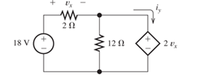
Figure P1.71
Expert Solution & Answer

Learn your wayIncludes step-by-step video

schedule04:28
Students have asked these similar questions
Identify elements that are in series in the circuit of Figure P1.31.
a series circuit contains a resistor and an inductor as shown in figure 1.3.14. determine a differential equation for the current i (t) if the resistance is R, the inductance is L, and the impressed voltage is E(t)
lell
L1
R
Ro
2. In this figure, assume arbitrary numbers for R1, R2, L1, and L2 including
some number for the battery E. Find the rate of current in which inductor one
(L1) is changing just after the switch is closed. Next, find the current in L1
after some time after the switch has been closed.
lell
Chapter 1 Solutions
EBK ELECTRICAL ENGINEERING
Ch. 1 - Broadly speaking, what are the two main objectives...Ch. 1 - Prob. 1.2PCh. 1 - List eight subdivisions of electrical engineering.Ch. 1 - Prob. 1.4PCh. 1 - Prob. 1.5PCh. 1 - In the fluid-flow analogy for electrical circuits,...Ch. 1 - The charge of an electron is 1.601019C . A current...Ch. 1 - The ends of a length of wire are labeled a and b....Ch. 1 - The circuit element shown in Figure P1.9 has v=12V...Ch. 1 - Prob. 1.10P
Ch. 1 - The net charge through a cross section of a...Ch. 1 - The current through a particular circuit element...Ch. 1 - The current through a given circuit element is...Ch. 1 - The net charge through a cross section of a...Ch. 1 - A copper wire has a diameter of 2.05 mm and...Ch. 1 - A certain lead acid storage battery has a mass of...Ch. 1 - A circuit element having terminals a and b has...Ch. 1 - An electron moves through a voltage of 9 V from...Ch. 1 - A typical “deep-cycle” battery (used for electric...Ch. 1 - Define the term passive reference configuration....Ch. 1 - Compute the power for each element shown in Figure...Ch. 1 - The terminals of an electrical device are labeled...Ch. 1 - The terminals of a certain battery are labeled a...Ch. 1 - The element shown in Figure P1.24 I has v(t)=10V...Ch. 1 - The current and voltage of an electrical device...Ch. 1 - Suppose that the cost of electrical energy is...Ch. 1 - Figure P1.27 shows an ammeter (AM) and voltmeter...Ch. 1 - Repeat Problem P1.27 with the meters connected as...Ch. 1 - A certain type of D-cell battery that costs $0.50...Ch. 1 - The electronics aboard a certain sailboat consume...Ch. 1 - What s a node in an electrical circuit? Identify...Ch. 1 - State Kirchhoff’s current law.Ch. 1 - Two electrical elements are connected in series....Ch. 1 - Suppose that in the fluid-flow analogy for an...Ch. 1 - Identify elements that are in series in the...Ch. 1 - Consider the circuit shown in Figure P1.36. Which...Ch. 1 - Use KCL to find the values of ia, ic , and id for...Ch. 1 - Find the values of the other currents in Figure...Ch. 1 - Prob. 1.39PCh. 1 - State Kirchhoff’s voltage law.Ch. 1 - Consider the circuit shown in Figure P1.36. Which...Ch. 1 - Use KVL to solve for the voltages va , vb, and vc...Ch. 1 - Solve for the other voltages shown in Figure P1.43...Ch. 1 - Use KVL and KCL to solve for the labeled currents...Ch. 1 - Identify elements that are in parallel in Figure...Ch. 1 - Points a, b, c, and d appear in a certain circuit....Ch. 1 - In your own words, define an ideal conductor; an...Ch. 1 - Name four types of dependent sources and give the...Ch. 1 - State Ohm’s law, including references.Ch. 1 - Draw a circuit that contains a 5 resistance, a...Ch. 1 - Repeat Problem P1.50, placing all three elements...Ch. 1 - The resistance of a certain copper wire is 0.5. ....Ch. 1 - Draw a circuit that contains a 5 resistor, a 10-V...Ch. 1 - Draw a circuit that contains a 5 resistor, a 10-V...Ch. 1 - A power of 100 W is delivered to a certain...Ch. 1 - The voltage across a 10 resistor is given by...Ch. 1 - The voltage across a 10 resistor is given by...Ch. 1 - A certain wire has a resistance of 0.5 . Find the...Ch. 1 - Plot i versus v to scale for each of the parts of...Ch. 1 - Which of the following are self-contradictory...Ch. 1 - Consider the circuit shown in Figure P1.61. Find...Ch. 1 - Consider the circuit shown in Figure P1.62. Find...Ch. 1 - Consider the circuit shown in Figure P1.63. Find...Ch. 1 - Consider the circuit shown in Figure P1.64. Use...Ch. 1 - Determine the value of Ix in the circuit shown in...Ch. 1 - Consider the circuit shown in Figure P1.66. Figure...Ch. 1 - Prob. 1.67PCh. 1 - Consider the circuit shown in Figure P1.68. Figure...Ch. 1 - Solve for the currents shown in Figure P1.69....Ch. 1 - The circuit shown in Figure P1.70 contains a...Ch. 1 - Determine the value of vx and iy in the circuit...Ch. 1 - A 10-V independent voltage source is in series...Ch. 1 - A 10-V independent voltage source is in parallel...Ch. 1 - Consider the circuit shown in Figure P1.74. Figure...Ch. 1 - The circuit shown in Figure P1.75 contains a...Ch. 1 - For the circuit shown in Figure P1.76, solve for...Ch. 1 - For the circuit shown in Figure P1.77, solve for...Ch. 1 - Match each entry in Table T1.1(a) with the best...Ch. 1 - Prob. 1.2PTCh. 1 - The circuit of Figure T1.3 has I1=3A , I2=1A ,...Ch. 1 - The circuit shown in Figure T1.4 has Vs=12V ,...Ch. 1 - We are given Vs=15V , R=10 , and =0.3S for the...Ch. 1 - We are given i4=2A for the circuit of Figure T1.6....
Additional Engineering Textbook Solutions
Find more solutions based on key concepts
The switch in the bottom loop of Fig. P6.1 is closed at t = 0 and then opened at a later time t1. What is the d...
Fundamentals of Applied Electromagnetics (7th Edition)
Which elements (individual elements, not combinations of elements) of the networks in Fig. 7.64. are in series?...
Introductory Circuit Analysis (13th Edition)
Explain the meaning of the term object persistence.
Database Concepts (8th Edition)
Further modify the logic circuit from Problem 48 for a change in the input sensors where Open = LOW and Closed ...
Digital Fundamentals (11th Edition)
(a) Write the rate law for the following reactions assuming each reaction follows an elementary rate law. Give ...
Elements of Chemical Reaction Engineering (5th Edition) (Prentice Hall International Series in the Physical and Chemical Engineering Sciences)
The assembly consists of two A992 steel bolts AB and EF and an 6061-T6 aluminum rod CD. When the temperature is...
Mechanics of Materials (10th Edition)
Knowledge Booster


Learn more about
Need a deep-dive on the concept behind this application? Look no further. Learn more about this topic, electrical-engineering and related others by exploring similar questions and additional content below.Similar questions
- Basic Electrical EngineeringDraw symbols of electrical components. Note: You may use both IEC and NEMA symbols. - Conductors crossing but not connected- Conductors crossing and connected - DC source other than battery- DC generator- AC voltage source- Ideal current source- Ideal Voltage Source- Current Controlled Current Source- Current Controlled Voltage Source- Voltage Controlled Current Source - Voltage Controlled Voltage Sourcearrow_forwardIn the circuit below, we have a Zener Diode circuit with a load, RL. Use the same measurements for source voltage V1 and resistor R3 resistance as in the circuit schematic. V1 -15V R3 2700 D1 1N753A RL Determine the lowest possible value for the load RL, so that the voltage drop across it is equal to the Zener voltage. For your diode, use model Zener 1N753A. This diode has a Zener voltage of 6.2V, a Zener current of 60mA, a Zener impedence of 72, and a test current of 20mA.arrow_forwardFind the equivelent resistance of the circuit below. (Rin)Conduction diodes' resistance is 0Insulating diodes' resistance is infinite.R1 = 10 ohmarrow_forward
- 1) It can be accepted that D1 and D2 diodes are from the same family in the circuit given in the figure. a) output voltage, wwwiwwwww wwwww wwwwwwwwwwn w www w 0.33 k2 wwwwww wwwww E 10 V D Si D, Si b) the current flowing through the resistor, ww ww c) currents flowing through the diodes గ wl ww ww calculate. www ww +arrow_forwardIn the figure given we have u(t)=10- cosot [V]. We assume the diodes and the A-meter (A) to be ideal. a) Plot the waveform of the current flowing through the A-m in scale. b) What is the reading of the A-m, if it is moving-coil type? A u(t) R1 R2 c) What is the reading of the A-m, if it is moving-iron type? d) Calculate the power factor of the WHOLE structure. 5Ω 10Ωarrow_forwardliting Q9. For the circuit shown in Figure C9, Calculate the following i) Current through the Silicon diode (Isi). ii) Current through the Resistor R2 (1). iii) Current through the diode D4 (IGe4). iv) Voltage at points V3 and V4. Is D1. D2 Si Si oV4 RI 1.3K2 R3 2.7K R2 3K2 IGe4| 15V D5 Si 03 D4 Ge Ge V2 1V Figure C9arrow_forward
- PLS help me.arrow_forwardShown below is a diode circuit. If the input signal Vs = 31 Vp-p and the DC voltage Vdc = 8 V, what is the output voltage (in volts) of the circuit during the negative alteration? No need to show your solution. Just write your numeric answer on the space provided. Round off your answer to 2 decimal places. C1 ... + Vdc 1.0kn Vo Vs Si D1arrow_forwardWhat is the Boolean expression for Vout? Assume that diodes are ideal.arrow_forward
arrow_back_ios
SEE MORE QUESTIONS
arrow_forward_ios
Recommended textbooks for you
 Introductory Circuit Analysis (13th Edition)Electrical EngineeringISBN:9780133923605Author:Robert L. BoylestadPublisher:PEARSON
 Delmar's Standard Textbook Of ElectricityElectrical EngineeringISBN:9781337900348Author:Stephen L. HermanPublisher:Cengage Learning
 Programmable Logic ControllersElectrical EngineeringISBN:9780073373843Author:Frank D. PetruzellaPublisher:McGraw-Hill Education
 Fundamentals of Electric CircuitsElectrical EngineeringISBN:9780078028229Author:Charles K Alexander, Matthew SadikuPublisher:McGraw-Hill Education
 Electric Circuits. (11th Edition)Electrical EngineeringISBN:9780134746968Author:James W. Nilsson, Susan RiedelPublisher:PEARSON
 Engineering ElectromagneticsElectrical EngineeringISBN:9780078028151Author:Hayt, William H. (william Hart), Jr, BUCK, John A.Publisher:Mcgraw-hill Education,
Introductory Circuit Analysis (13th Edition)
Electrical Engineering
ISBN:9780133923605
Author:Robert L. Boylestad
Publisher:PEARSON
Delmar's Standard Textbook Of Electricity
Electrical Engineering
ISBN:9781337900348
Author:Stephen L. Herman
Publisher:Cengage Learning
Programmable Logic Controllers
Electrical Engineering
ISBN:9780073373843
Author:Frank D. Petruzella
Publisher:McGraw-Hill Education
Fundamentals of Electric Circuits
Electrical Engineering
ISBN:9780078028229
Author:Charles K Alexander, Matthew Sadiku
Publisher:McGraw-Hill Education
Electric Circuits. (11th Edition)
Electrical Engineering
ISBN:9780134746968
Author:James W. Nilsson, Susan Riedel
Publisher:PEARSON
Engineering Electromagnetics
Electrical Engineering
ISBN:9780078028151
Author:Hayt, William H. (william Hart), Jr, BUCK, John A.
Publisher:Mcgraw-hill Education,
[2015] Engineering Fundamentals 02: Unit systems. SI unit system [with closed caption]; Author: Yiheng Wang;https://www.youtube.com/watch?v=cryvZJ0KNqk;License: Standard YouTube License, CC-BY