
Concept explainers
Videos
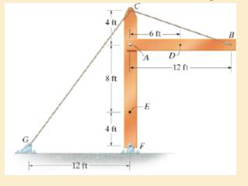
The beam AB is pin supported at A and supported by a cable BC. A separate cable CG is used to hold up the frame. If AB weighs 120 lb/ft and the column FC has a weight of 180 lb/ft, determine the resultant internal loadings acting on cross sections located at points D and E.
Answer to Problem 1RP
The resultant internal loadings at cross section at D are
The resultant internal loadings at cross section at E are
Explanation of Solution
Given information:
The beam AB is pin supported at A and supported by a cable BC.
The weight of the beam AB is
The weight of the column FC is
Calculation:
Find the loading at the center of the beam AB
Substitute
Convert the unit from lb to kip.
Sketch the Free Body Diagram of the beam AB shown in Figure 1.
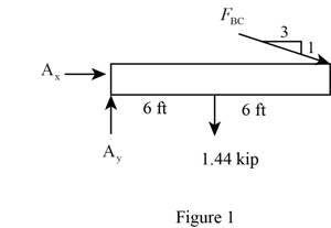
Refer to Figure 1.
Find the angle of cable BC to the horizontal
Find the tension in cable BC as shown below.
Take moment about A is Equal to zero.
Find the support reaction at A as shown below.
Apply the Equations of Equilibrium as shown below.
Summation of forces along horizontal direction is Equal to zero.
Summation of forces along vertical direction is Equal to zero.
Find the loading at the center of the beam AD
Substitute
Convert the unit from lb to kip.
Sketch the Free Body Diagram of the section for point D as shown in Figure 2.
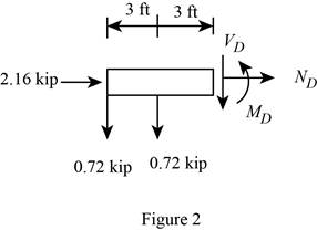
Refer to Figure 2.
Find the internal loadings as shown below.
Apply the Equations of Equilibrium as shown below.
Summation of forces along horizontal direction is Equal to zero.
Summation of forces along vertical direction is Equal to zero.
Take moment about D is Equal to zero.
Hence, the resultant internal loadings at cross section at D are
Find the loading at the center of the column FC
Substitute
Convert the unit from lb to kip.
Sketch the Free Body Diagram of the beam FC shown in Figure 3.
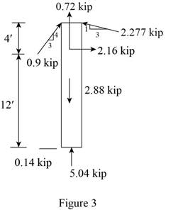
Refer to Figure 3.
Find the angle of cable CG to the horizontal.
Find the tension in cable CG as shown below.
Summation of forces along horizontal direction is Equal to zero.
Find the loading at the center of the column FE
Substitute
Convert the unit from lb to kip.
Sketch the Free Body Diagram of the section for point E as shown in Figure 4.
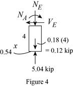
Refer to Figure 4.
Find the internal loadings as shown below.
Apply the Equations of Equilibrium as shown below.
Summation of forces along horizontal direction is Equal to zero.
Summation of forces along vertical direction is Equal to zero.
Take moment about E is Equal to zero.
Therefore, the resultant internal loadings at cross section at E are
Want to see more full solutions like this?
Chapter 1 Solutions
Mechanics of Materials
Additional Engineering Textbook Solutions
Automotive Technology: Principles, Diagnosis, And Service (6th Edition) (halderman Automotive Series)
Thinking Like an Engineer: An Active Learning Approach (4th Edition)
Statics and Mechanics of Materials (5th Edition)
Applied Statics and Strength of Materials (6th Edition)
Thinking Like an Engineer: An Active Learning Approach (3rd Edition)
Engineering Mechanics: Statics & Dynamics (14th Edition)


- The beam shown has an overall length L of 6.9 metres. A uniform distributed load of 3.9 kN/m is applied as shown. If the distance x is 1.9 metres, determine the magnitude (in kNm) of the reaction moment at A. Note: Do NOT include the units in your answer.arrow_forwardFind the support reactions at the fixed support O. The beam has a mass of 500 kg, and it has a uniform cross section. 1.2 m A 1.4 kN 1.8 m 15 kN.m B ● 1.8 m 30° 3 kN xarrow_forward4. Determine the force at roller B if a 15 mm gap resulted from a construction error. Compare the maximum moment in the beam to the case if no gap existed. The steel beam is a W250x32.7 16 kN/m B 15 mm 4 m 6 marrow_forward
- The vertical load on the hook is 1000 lb. Draw the appropriate free-body diagrams and determine the maximum average shear force on the pins at A, B, and C. Note that due to symmetry four wheels are used to support the loading on the railing.arrow_forward2-13.10. A beam of length L supports a load which varies uniformly from w lb/ft at the right end to zero at the left end. Show that the resultant load is W = wL/2 acting at L/3 from the right end.arrow_forwardThe 440-kg uniform beam is subjected to the three external loads shown. Compute the reactions at the support point O. The x-y plane is vertical. Positive values are to the right, up, and counterclockwise. y 41 kN-m B HÖZ 4.8 KN 1.7 m 1.1 m Answers: Ox= Oy= i Mo= i i A kN kN 1.7 m kN.m 27 2.7 KN xarrow_forward
- The 460-kg uniform beam is subjected to the three external loads shown. Compute the reactions at the support point O. The x-y plane is vertical. Positive values are to the right, up, and counterclockwise. 0 1.2 m Answers: Ox Oy = i Mo= i i A 6.1 KN 1.6 m 19 kN.m B kN kN 1.6 m kN-m 20 C 2.7 KN -1xarrow_forwardDetermine the resultant of the line load acting on the beam shown in Fig. (a) Can u please help mearrow_forwardFor the rigid body shown, determine the support reactions at the pin and roller. 30 lb/ft 180 lb · ft A B C 9 ft - -4.5 ftarrow_forward
- Please help me with thisarrow_forwardW 6 ft A D -4 ft- + B -4 ft C Determine the normal force at point b using method of section if w = 52.1lb/ftarrow_forwardThe 470-kg uniform beam is subjected to the three external loads shown. Compute the reactions at the support point O. The x-y plane is vertical. Positive values are to the right, up, and counterclockwise. 15 kN m 38 3.6 kN A B Höy 2.6 KN 1.3 m 2.0 m 2.0 m Answers: i 3 i Mo- kN KN kN-marrow_forward
 International Edition---engineering Mechanics: St...Mechanical EngineeringISBN:9781305501607Author:Andrew Pytel And Jaan KiusalaasPublisher:CENGAGE L