
Videos
Determine the output of each of the following circuits, assuming that the upper input is 1 and the lower input is 0 What would be the output when the upper input is 0 and the lower input is 1?
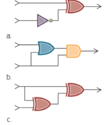
a.
Explanation of Solution
Determine the output of the given circuit.
The stated diagram is shown below,
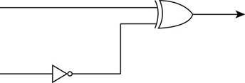
- To find the output of the circuit when the upper input is 1 and the lower input is 0, the diagram contains one XOR gate and inverter, so the Boolean operation of XOR gate and inverter is shown below:
The Boolean XOR operation is shown in table below,
| Input 1 | Input 2 | Output |
| 0 | 0 | 0 |
| 0 | 1 | 1 |
| 1 | 0 | 1 |
| 1 | 1 | 0 |
- First, 0 is the input of inverter which gives the output of inverter and this output of the inverter is the lower input of XOR gate.
The inverter operation is shown in table below,
| Input | output |
| 1 | 0 |
| 0 | 1 |
- The lower input 0 is converted to 1 through inverter gate that means the lower input of XOR gate is 1.
The inputs of XOR gate are shown in Figure below,
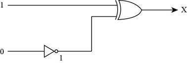
- To represent the output of XOR gate, convert the input of XOR gate through Boolean operation, when both the inputs of XOR gate is 1, then the output of the XOR gate is 0 by Boolean operation XOR table.
Therefore, the required output of the given circuit is “0”.
Determine the output of the given circuit, when the upper input is 0 and the lower input is 1:
- To find the output of the circuit when the upper input is 0 and the lower input is 1, the diagram contains one XOR gate and inverter:
- First, 1 is the input of inverter which gives the output of the inverter and this output of the inverter is the lower input of XOR gate.
- The lower input 1 is converted to 0 through inverter gate, so the lower input of XOR gate is 0.
The inputs of XOR gate are shown in Figure below,
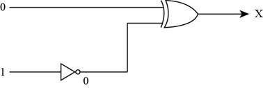
- To represent the output of XOR gate, convert the input of XOR gate through Boolean operation, when both the inputs of XOR gate is 0, then the output of the XOR gate is 1 by Boolean operation XOR table.
Therefore, the required output of the given circuit is “1”.
b.
Explanation of Solution
Determine the output of the given circuit.
The stated diagram is shown below,
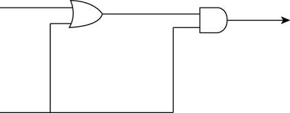
- To find the output of the circuit when the upper input is 1 and the lower input is 0, the diagram contains one OR gate and one AND gate, so the Boolean operation of OR gate and one AND gate is shown below:
The Boolean OR operation is shown in table below,
| Input 1 | Input 2 | output |
| 0 | 0 | 0 |
| 0 | 1 | 1 |
| 1 | 0 | 1 |
| 1 | 1 | 1 |
- First, 1 and 0 are the inputs of OR gate that give the output of the OR gate and this output of OR gate is the upper input of AND gate.
The Boolean AND operation is shown in table below,
| Input 1 | Input 2 | output |
| 0 | 0 | 0 |
| 0 | 1 | 0 |
| 1 | 0 | 0 |
| 1 | 1 | 1 |
The upper input 1 and lower input 0 is converted to 1 through OR gate, so the upper input of AND gate is 1.
The inputs of AND gate are shown in Figure below,
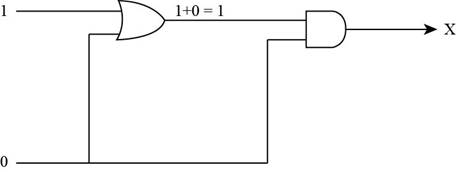
- To represent the output of AND gate, convert the input of AND gate through Boolean operation, when the upper input is 1 and lower input is 0 of AND gate, then the output of the AND gate is 0 by Boolean operation AND table.
Therefore, the required output for the given circuit is “0”.
Determine the output of the given circuit, when the upper input is 0 and the lower input is 1:
- To find the output of the circuit when the upper input is 0 and the lower input is 1, the diagram contains one OR gate and one AND gate:
- First, 0 and 1 is the input of OR gate that gives the output of the OR gate which is the upper input of the AND gate.
The upper input 0 and lower input 1 is converted to 1 through OR gate, so the upper input of AND gate is 1.
The inputs of AND gate are shown in Figure below,
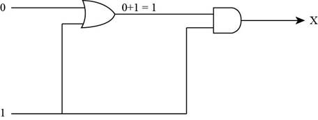
Figure (6)
- To represent the output of AND gate, convert the input of AND gate through Boolean operation, when both the inputs of AND gate is 1 then the output of the AND gate is 1 by Boolean operation AND table.
Therefore, the required output for the given circuit is “1”.
c.
Explanation of Solution
Determine the output of the given circuit:
The stated diagram is shown below,
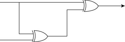
- To find the output of the circuit when the upper input is 1 and the lower input is 0, the diagram contains two XOR gates, so the Boolean operation of XOR gates as shown below:
The Boolean XOR operation is shown in table below,
| Input 1 | Input 2 | output |
| 0 | 0 | 0 |
| 0 | 1 | 1 |
| 1 | 0 | 1 |
| 1 | 1 | 0 |
- First, 1 and 0 are the inputs of XOR gate that give the output of the first XOR gate which is the lower input of second XOR gate.
The upper input 1 and lower input 0 are converted to 1 through XOR gate, so the lower input of second XOR gate is 1.
The inputs of XOR gate are shown in Figure below,
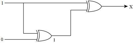
- To represent the output of XOR gate, convert the input of XOR gate through Boolean operation, when both the inputs of XOR gate become 1, then the output of the XOR gate becomes 0 by Boolean operation XOR table.
Therefore, the required output for the given circuit is “0”.
Determine the output of the given circuit, when the upper input is 0 and the lower input is 1:
- To find the output of the circuit when the upper input is 0 and the lower input is 1, the diagram contains two XOR gates:
- First, 0 and 1 are the inputs of first XOR gate that give the output of the first XOR gate which is the lower input of second XOR gate.
The upper input 1 and lower input 0 are converted to 1 through XOR gate, so the lower input of second XOR gate is 1.
The inputs of XOR gate are shown in Figure below,
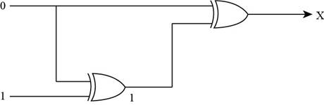
- To represent the output of XOR gate, convert the input of XOR gate through Boolean operation, when the upper input is 0 and lower input is 1 of XOR gate, then the output of the XOR gate is 1 by Boolean operation XOR table.
Therefore, the required output for the given circuit is “1”.
Want to see more full solutions like this?
Chapter 1 Solutions
COMPUTER SCIENCE:OVERVIEW-TEXT
Additional Engineering Textbook Solutions
Database Concepts (7th Edition)
Starting Out with C++: Early Objects
Problem Solving with C++ (10th Edition)
Introduction To Programming Using Visual Basic (11th Edition)
Starting Out with Java: From Control Structures through Objects (6th Edition)


- Design a combinational circuit that increments the 4-bit binary input. The output of the circuit is also represented as 4 bits. For example, if the input is 0011 then the output is 0100. Note: the increment of 1111 is 0000. Let the input variables be A, B, C, and D, while the output variables be W, X, Y, and Z. What is the boolean function (in sum of minterm format) of output W? What is the boolean function (in sum of minterm format) of output X? What is the boolean function (in sum of minterm format) of output Y? What is the boolean function (in sum of minterm format) of output Z?arrow_forwardFind the output (Y) of the following circuit, and then design a simpler circuit having the same function: D B A- B B- DAD Yarrow_forwardAnswer the given questionarrow_forward
- implement the following circuit. Write the boolean expression describing its outputsarrow_forwardDesign a circuit with 3 inputs and 3 outputs, when the binary input is m0, m1, m2 and m3 the output is input plus two and when the input is m4, m5, m6 and m7 then the output is three less then input use k-Map to get the simplified circuit.arrow_forward2. Write the Boolean equation directly from the following circuit. Aarrow_forward
- AO- For the above given logic circuit, the output Y value is =1 when the inputs of A, B, and C are a. None of these O b. A=1, B=1, C=1 O c. A=1, B=1, C=0 O d. A=1, B=0, C=1arrow_forwardDesign a circuit to implement the following truth table, where A and B are inputs and Z is the output. Give the Boolean equation that implements the circuit in the space provided. There may be more than one possible correct answer. You only need to list one possible correct answer. Input Output A B Z 0 0 1 0 1 0 1 0 1 1 1 1arrow_forwardX y Z 21. What is the output of the following circuit? x+yarrow_forward
- A combinational circuit is to be designed which takes 4 inputs and one output. The output = 1, if the digit >= 6, and 0 otherwise. If only AND, OR and NOT gates may be used, what is the minimum number of gates required? Select one: O 2 O O 5 How do you make an AND gate out of an OR gate using inverters (NOT gates)? Select one: O Invert the output from the OR gate O Invert both the inputs to the OR gate O Invert one of the inputs to the OR gate O Invert both the inputs and output of the OR gatearrow_forward1. Use the 2-input version of the basic AND, OR, NOT gates to implement the following Boolean expression. Insert a drawing of your circuit here. Expression: (A + B)č. Use the 2-input version of the basic AND, OR, NOT gates to implement the following Boolean expression. Insert a drawing of your circuit here. Expression: (AB)(BC). Write the Boolean expression that is equivalent to the following circuit. D 2. Use the Word table tool to construct the truth table for this circuit. Be sure to include intermediate values. Insert columradings in the first row. Be sure to use the Insert > Equation tool so that standard Boolean logic symbols are displayed in the headings.arrow_forwardDADD Find the expression output of the circuit and simplify the expression output using Boolean algebra and identities. Implement the circuit by using a Multiplexer.arrow_forward
 Database System ConceptsComputer ScienceISBN:9780078022159Author:Abraham Silberschatz Professor, Henry F. Korth, S. SudarshanPublisher:McGraw-Hill Education
 Starting Out with Python (4th Edition)Computer ScienceISBN:9780134444321Author:Tony GaddisPublisher:PEARSON
 Digital Fundamentals (11th Edition)Computer ScienceISBN:9780132737968Author:Thomas L. FloydPublisher:PEARSON
 C How to Program (8th Edition)Computer ScienceISBN:9780133976892Author:Paul J. Deitel, Harvey DeitelPublisher:PEARSON
 Database Systems: Design, Implementation, & Manag...Computer ScienceISBN:9781337627900Author:Carlos Coronel, Steven MorrisPublisher:Cengage Learning
 Programmable Logic ControllersComputer ScienceISBN:9780073373843Author:Frank D. PetruzellaPublisher:McGraw-Hill Education