
Videos
Determine the output of each of the following circuits, assuming that the upper input is 1 and the lower input is 0 What would be the output when the upper input is 0 and the lower input is 1?
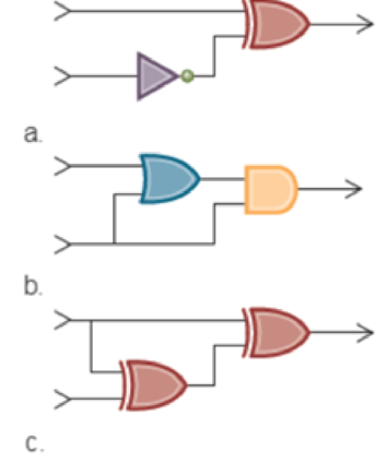
a.
Explanation of Solution
Determine the output of the given circuit.
The stated diagram is shown below,
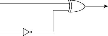
- To find the output of the circuit when the upper input is 1 and the lower input is 0, the diagram contains one XOR gate and inverter, so the Boolean operation of XOR gate and inverter is shown below:
The Boolean XOR operation is shown in table below,
| Input 1 | Input 2 | Output |
| 0 | 0 | 0 |
| 0 | 1 | 1 |
| 1 | 0 | 1 |
| 1 | 1 | 0 |
- First, 0 is the input of inverter which gives the output of inverter and this output of the inverter is the lower input of XOR gate.
The inverter operation is shown in table below,
| Input | output |
| 1 | 0 |
| 0 | 1 |
- The lower input 0 is converted to 1 through inverter gate that means the lower input of XOR gate is 1.
The inputs of XOR gate are shown in Figure below,
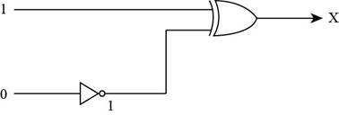
- To represent the output of XOR gate, convert the input of XOR gate through Boolean operation, when both the inputs of XOR gate is 1, then the output of the XOR gate is 0 by Boolean operation XOR table.
Therefore, the required output of the given circuit is “0”.
Determine the output of the given circuit, when the upper input is 0 and the lower input is 1:
- To find the output of the circuit when the upper input is 0 and the lower input is 1, the diagram contains one XOR gate and inverter:
- First, 1 is the input of inverter which gives the output of the inverter and this output of the inverter is the lower input of XOR gate.
- The lower input 1 is converted to 0 through inverter gate, so the lower input of XOR gate is 0.
The inputs of XOR gate are shown in Figure below,
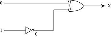
- To represent the output of XOR gate, convert the input of XOR gate through Boolean operation, when both the inputs of XOR gate is 0, then the output of the XOR gate is 1 by Boolean operation XOR table.
Therefore, the required output of the given circuit is “1”.
b.
Explanation of Solution
Determine the output of the given circuit.
The stated diagram is shown below,
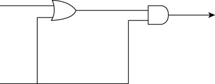
- To find the output of the circuit when the upper input is 1 and the lower input is 0, the diagram contains one OR gate and one AND gate, so the Boolean operation of OR gate and one AND gate is shown below:
The Boolean OR operation is shown in table below,
| Input 1 | Input 2 | output |
| 0 | 0 | 0 |
| 0 | 1 | 1 |
| 1 | 0 | 1 |
| 1 | 1 | 1 |
- First, 1 and 0 are the inputs of OR gate that give the output of the OR gate and this output of OR gate is the upper input of AND gate.
The Boolean AND operation is shown in table below,
| Input 1 | Input 2 | output |
| 0 | 0 | 0 |
| 0 | 1 | 0 |
| 1 | 0 | 0 |
| 1 | 1 | 1 |
The upper input 1 and lower input 0 is converted to 1 through OR gate, so the upper input of AND gate is 1.
The inputs of AND gate are shown in Figure below,
- To represent the output of AND gate, convert the input of AND gate through Boolean operation, when the upper input is 1 and lower input is 0 of AND gate, then the output of the AND gate is 0 by Boolean operation AND table.
Therefore, the required output for the given circuit is “0”.
Determine the output of the given circuit, when the upper input is 0 and the lower input is 1:
- To find the output of the circuit when the upper input is 0 and the lower input is 1, the diagram contains one OR gate and one AND gate:
- First, 0 and 1 is the input of OR gate that gives the output of the OR gate which is the upper input of the AND gate.
The upper input 0 and lower input 1 is converted to 1 through OR gate, so the upper input of AND gate is 1.
The inputs of AND gate are shown in Figure below,
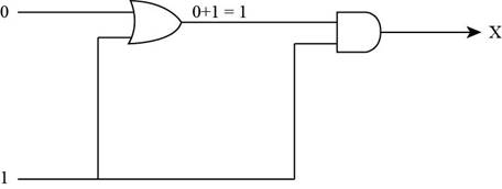
Figure (6)
- To represent the output of AND gate, convert the input of AND gate through Boolean operation, when both the inputs of AND gate is 1 then the output of the AND gate is 1 by Boolean operation AND table.
Therefore, the required output for the given circuit is “1”.
c.
Explanation of Solution
Determine the output of the given circuit:
The stated diagram is shown below,
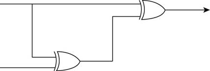
- To find the output of the circuit when the upper input is 1 and the lower input is 0, the diagram contains two XOR gates, so the Boolean operation of XOR gates as shown below:
The Boolean XOR operation is shown in table below,
| Input 1 | Input 2 | output |
| 0 | 0 | 0 |
| 0 | 1 | 1 |
| 1 | 0 | 1 |
| 1 | 1 | 0 |
- First, 1 and 0 are the inputs of XOR gate that give the output of the first XOR gate which is the lower input of second XOR gate.
The upper input 1 and lower input 0 are converted to 1 through XOR gate, so the lower input of second XOR gate is 1.
The inputs of XOR gate are shown in Figure below,
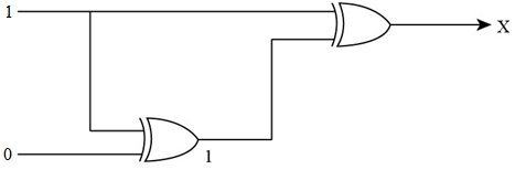
- To represent the output of XOR gate, convert the input of XOR gate through Boolean operation, when both the inputs of XOR gate become 1, then the output of the XOR gate becomes 0 by Boolean operation XOR table.
Therefore, the required output for the given circuit is “0”.
Determine the output of the given circuit, when the upper input is 0 and the lower input is 1:
- To find the output of the circuit when the upper input is 0 and the lower input is 1, the diagram contains two XOR gates:
- First, 0 and 1 are the inputs of first XOR gate that give the output of the first XOR gate which is the lower input of second XOR gate.
The upper input 1 and lower input 0 are converted to 1 through XOR gate, so the lower input of second XOR gate is 1.
The inputs of XOR gate are shown in Figure below,
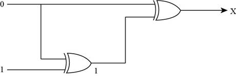
- To represent the output of XOR gate, convert the input of XOR gate through Boolean operation, when the upper input is 0 and lower input is 1 of XOR gate, then the output of the XOR gate is 1 by Boolean operation XOR table.
Therefore, the required output for the given circuit is “1”.
Want to see more full solutions like this?
Chapter 1 Solutions
Computer Science: An Overview (12th Edition)
Additional Engineering Textbook Solutions
Database Concepts (7th Edition)
Starting Out with C++: Early Objects
Problem Solving with C++ (10th Edition)
Introduction To Programming Using Visual Basic (11th Edition)
Starting Out with Java: From Control Structures through Objects (6th Edition)


- Based on the following image answer the following questions; a. Write a boolean algebra expression for each of Q0, Q1, Q2, and Q3: b. Draw a circuit that produces each of the functions from a single set of inputs A1 and A0: c. Each input combination of A1 and A0 represents a 2-bit binary number. How is this related to the outputs?arrow_forwardDesign a combinational circuit with three inputs x, y, and z, and three outputs, A, B, and C. When the binary input is 0, 1, 2, or 3, the binary output is one greater than the input. For example, if the inputs are 000, the outputs are 001. When the binary input is 4, 5, 6, or 7, the binary output is two less than the input. For example, when inputs are100, the outputs are 010. Show the truth table for the inputs and outputs. please show all steps , dont just explainarrow_forwardChose the correct answer for the output F of the following circuit ( Assume that A= 101010, B= 100101, C=111101 and D =110100 and the first bit out from the circuit is bit 0)*arrow_forward
- Draw the circuit diagram of a 2-digit calculator that adds, subtracts, multiplies and divides and can add up to 99.arrow_forwardConsider a circuit that takes the numbers 0 through 7 as inputs (0=000,1=001, 2=010, ..., 7=111) and produces an output of 1 if and only if the input is an odd number). Write the function and simplify.arrow_forwardImplement the TRUTH TABLE of the following state machine and DRAW the SCHEMATIC CIRCUITarrow_forward
- Use pencil and paper to solve this question. 1.. Construct a circuit for the following Boolean expressions : I. ( ~p V ~q) Λ (~p Λ r) Λ (q V~r) II. P∧∼Q) ∨(∼P∧R)arrow_forwardAnalyze the following sequential circuit with E external input and Z output. DA=E’AB+A’DB= A xor B + E’ABZ=ABarrow_forwardDesign a circuit that takes three bits, X2, X1, X0 as input and produces one output, F. F is 1 if and only if 2<=X<=5 when X = (X2, X1, X0) is read as an unsigned integer. For example, if X2=1, X1=0, and X0=0, then the unsigned binary value is 100, which is 4, so the output would be 1. Your Assignment For This Problem Includes the Following Design the necessary circuit using Logisim to implement the situation described above. Use Kmaps for simplification. Be VERY careful to get the correct functions for your output before simplifying and designing the circuit with Logisim. You should minimize the circuit. Your circuit should have three inputs and one LED output. All inputs (X2, X1, X0) and output (F) should be labeled (in Logisim, not by hand). Please use these names to indicate the inputs and output so all projects are consistent. You should also include your name as a label on the circuit. Test your circuit to be sure it is working correctly.arrow_forward
- Design a circuit that compares two 3-bit numbers A and B to check if they are equal and less than. The circuit has two outputs X and Y, So that X=1 if A==B and X=0 if A!=B and Y=1 if A<B and Y=0 if A>Barrow_forwardboolean expression: P = not((not(a.b) + c) + a.c) (c) Show that P (the Boolean expression above) is equivalent to the Boolean expression Q = a · b · not(c) and draw the corresponding circuit.arrow_forwardGiven the below Function: Draw the combinational circuit that directly implements the Boolean expression: For what values of x, y, and z the output (F) will be 0? Justify your answer using a truth table.arrow_forward
 Database System ConceptsComputer ScienceISBN:9780078022159Author:Abraham Silberschatz Professor, Henry F. Korth, S. SudarshanPublisher:McGraw-Hill Education
 Starting Out with Python (4th Edition)Computer ScienceISBN:9780134444321Author:Tony GaddisPublisher:PEARSON
 Digital Fundamentals (11th Edition)Computer ScienceISBN:9780132737968Author:Thomas L. FloydPublisher:PEARSON
 C How to Program (8th Edition)Computer ScienceISBN:9780133976892Author:Paul J. Deitel, Harvey DeitelPublisher:PEARSON
 Database Systems: Design, Implementation, & Manag...Computer ScienceISBN:9781337627900Author:Carlos Coronel, Steven MorrisPublisher:Cengage Learning
 Programmable Logic ControllersComputer ScienceISBN:9780073373843Author:Frank D. PetruzellaPublisher:McGraw-Hill Education