
Bundle: Principles Of Geotechnical Engineering, Loose-leaf Version, 9th + Mindtap Engineering, 1 Term (6 Months) Printed Access Card
9th Edition
ISBN: 9781337583848
Author: Braja M. Das, Khaled Sobhan
Publisher: Cengage Learning
expand_more
expand_more
format_list_bulleted
Concept explainers
Videos
Textbook Question
Chapter 10, Problem 10.12P
Refer to Figure 10.43. A strip load of q = 1450 lb/ft2 is applied over a width with B = 48 ft. Determine the increase in vertical stress at point A located z = 21 ft below the surface. Given x = 28.8 ft.
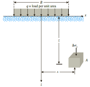
Figure 10.43
Expert Solution & Answer

Trending nowThis is a popular solution!

Students have asked these similar questions
4- A strip load of q= 100 lb/ft is applied over a width, B=10 ft. Determine the increase in vertical stress at point A
located z =4.6 ft below the surface. Given: x-8.2 ft.
q = load per unit arca
The rectangular bar shown in the figure is subjected to a uniformly distributed axial loading of w = 11 kN/m and a concentrated force of P = 14 kN at B. Determine the magnitude of the maximum normal stress in the bar and its location x. Assume a = 0.9 m, b = 1.1 m, c = 20 mm, and d = 35 mm.
ELABORATE
Try solving the following problem:
Practice Problem: Refer to Figure 3.12. Determine the
vertical stress increase Aoz, at point A with the following
values: q = 75 lb/ft; x = 6 ft;
z = 5 ft.
STAR
Line load = q
Figure 3.12
Aσ₂
Chapter 10 Solutions
Bundle: Principles Of Geotechnical Engineering, Loose-leaf Version, 9th + Mindtap Engineering, 1 Term (6 Months) Printed Access Card
Ch. 10 - Prob. 10.1PCh. 10 - Prob. 10.2PCh. 10 - Prob. 10.3PCh. 10 - Prob. 10.4PCh. 10 - Prob. 10.5PCh. 10 - Prob. 10.6PCh. 10 - Point loads of magnitude 125, 250, and 500 kN act...Ch. 10 - Refer to Figure 10.41. Determine the vertical...Ch. 10 - For the same line loads given in Problem 10.8,...Ch. 10 - Refer to Figure 10.41. Given: q2 = 3800 lb/ft, x1...
Ch. 10 - Refer to Figure 10.42. Due to application of line...Ch. 10 - Refer to Figure 10.43. A strip load of q = 1450...Ch. 10 - Repeat Problem 10.12 for q = 700 kN/m2, B = 8 m,...Ch. 10 - Prob. 10.14PCh. 10 - For the embankment shown in Figure 10.45,...Ch. 10 - Refer to Figure 10.46. A flexible circular area of...Ch. 10 - Refer to Figure 10.47. A flexible rectangular area...Ch. 10 - Refer to the flexible loaded rectangular area...Ch. 10 - Prob. 10.19PCh. 10 - Prob. 10.20PCh. 10 - Refer to Figure 10.48. If R = 4 m and hw = height...Ch. 10 - Refer to Figure 10.49. For the linearly increasing...Ch. 10 - EB and FG are two planes inside a soil element...Ch. 10 - A soil element beneath a pave ment experiences...
Knowledge Booster


Learn more about
Need a deep-dive on the concept behind this application? Look no further. Learn more about this topic, civil-engineering and related others by exploring similar questions and additional content below.Similar questions
- Refer to Figure 10.46. A flexible circular area of radius 6 m is uniformly loaded. Given: q = 565 kN/m2. Using Newmarks chart, determine the increase in vertical stress, z, at point A. Figure 10.46arrow_forwardUse Eq. (6.14) to determine the stress increase () at z = 10 ft below the center of the area described in Problem 6.5. 6.5 Refer to Figure 6.6, which shows a flexible rectangular area. Given: B1 = 4 ft, B2 = 6 ft, L1, = 8 ft, and L2 = 10 ft. If the area is subjected to a uniform load of 3000 lb/ft2, determine the stress increase at a depth of 10 ft located immediately below point O. Figure 6.6 Stress below any point of a loaded flexible rectangular areaarrow_forwardRepeat Problem 10.12 for q = 700 kN/m2, B = 8 m, and z = 4 m. In this case, point A is located below the centerline under the strip load. 10.12 Refer to Figure 10.43. A strip load of q = 1450 lb/ft2 is applied over a width with B = 48 ft. Determine the increase in vertical stress at point A located z = 21 ft below the surface. Given x = 28.8 ft. Figure 10.43arrow_forward
- What is/are the advantages of knowing how to estimate the additional stress/es due to surface/structural loads? Explain your answer/s. solve the followingarrow_forward6 decimal places for the solutionarrow_forwardELABORATE Try solving the following problem: Practice Problem: Refer to Figure 3.8. Determine the vertical stress increaseÃO₂, at point A with the following values: q = 750 lb/ft; x = 8 ft; z = 3 ft. !! Line load = q xarrow_forward
- www Problem 2 For the stress conditions given, determine the Maximum Shear Stress (Tmax) value from the Mohr Circle. 18 psi 26.5° 16 psi 20 45⁰ 30arrow_forwardHello, I’m struggling help me please show all the work.arrow_forwardDetermine the normal stress developed at points A, B, and C. The diameter of each segment is indicated in the figure. (Note = 1 kip = 1,000 lbs) 1 in. 0.5 in. 0.5 in. B. 3 kip A |9 kip |8 kip | c 2 kiparrow_forward
- Point loads of magnitude 2000, 4000, and 6000 lb act at A, B, and C, respectively as shown. Determine the increase in vertical stress at a depth of 10 ft below point D. Use Boussinesq's equation. a. 110.4 psf b. 89.23 psf C. 106.82 psf d. 99.9 psfarrow_forwardQuestion 03: Determine the normal stress and draw the stress diagram of the beam at a point 1 m from the left support. 1.0m 20KN/M D ↓ ↓ ↓ ↓ J J 2.0m 1=225x106mm² Bean depth = z 300mmarrow_forwardRefer to figure below. The magnitude of the load is 120 kPa. Calculate the vertical stress at points, A , B, and C. 3 т 2 m |120 kPa B. 2 marrow_forward
arrow_back_ios
SEE MORE QUESTIONS
arrow_forward_ios
Recommended textbooks for you
 Principles of Geotechnical Engineering (MindTap C...Civil EngineeringISBN:9781305970939Author:Braja M. Das, Khaled SobhanPublisher:Cengage Learning
 Principles of Foundation Engineering (MindTap Cou...Civil EngineeringISBN:9781305081550Author:Braja M. DasPublisher:Cengage Learning
 Fundamentals of Geotechnical Engineering (MindTap...Civil EngineeringISBN:9781305635180Author:Braja M. Das, Nagaratnam SivakuganPublisher:Cengage Learning
 Principles of Foundation Engineering (MindTap Cou...Civil EngineeringISBN:9781337705028Author:Braja M. Das, Nagaratnam SivakuganPublisher:Cengage Learning
Principles of Geotechnical Engineering (MindTap C...
Civil Engineering
ISBN:9781305970939
Author:Braja M. Das, Khaled Sobhan
Publisher:Cengage Learning
Principles of Foundation Engineering (MindTap Cou...
Civil Engineering
ISBN:9781305081550
Author:Braja M. Das
Publisher:Cengage Learning
Fundamentals of Geotechnical Engineering (MindTap...
Civil Engineering
ISBN:9781305635180
Author:Braja M. Das, Nagaratnam Sivakugan
Publisher:Cengage Learning
Principles of Foundation Engineering (MindTap Cou...
Civil Engineering
ISBN:9781337705028
Author:Braja M. Das, Nagaratnam Sivakugan
Publisher:Cengage Learning
Stress Distribution in Soils GATE 2019 Civil | Boussinesq, Westergaard Theory; Author: Gradeup- GATE, ESE, PSUs Exam Preparation;https://www.youtube.com/watch?v=6e7yIx2VxI0;License: Standard YouTube License, CC-BY