
The model parameters for an NMOS transistor operating at different values
Answer to Problem 10.1P
Explanation of Solution
Given:
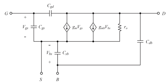
Fig: Given NMOS transistor
Calculation:
The equation for oxide capacitance is given by,
Plugging the values
The equation for overdrive voltage is given by,
Plugging the values
Here,
The equation for transconductance is given by,
Plugging the values
The equation for the body trans conductance is given by,
Plugging the values
The equation for the output resistance through the transistor is given by,
Plugging the values
Plugging the values
The equation for gate-source capacitance is given by,
Plugging the values
The equation for the source body capacitance is given by,
Plugging the values
The equation for drain body capacitance is given by,
Plugging the values
The equation for unity gain frequency is given by,
Plugging the values
Want to see more full solutions like this?
Chapter 10 Solutions
MICROLEECTRONIC E BOOKS

- Determine the Norton equivalent of the circuit in Fig. 10.30 as seen fromterminals a‑b. Use the equivalent to find Io ?arrow_forwardA satellite prototype is using a 2.4 GHz radio for wireless communication.What is the signal period (with ps resolution?) Note that 1GHZ - 10^9 Hz and 1ps = 10^-12 s.arrow_forwardA superheterodyne receiver is to tune the range 88.1MHz to 107.1MHz. The RF circuit inductance is 1μH. Low-side injection is used.a. Calculate the minimum capacitance of the variable capacitor in the RF circuitb. Calculate the RF circuit capacitance tuning ratio c. If the receiver has a single converter stage and IF of 800kHz, calculate the capacitance tuning ratio of the local oscillator d. If the maximum capacitance of the variable capacitor of the local oscillator is 0.2pF, calculate the minimum capacitance e. If the receiver has a single converter stage and IF of 800kHz, calculate the image frequency of 103.7MHzf. Calculate the IFRR (in dB) of (e) if Q of the preselector is 50 g. To increase the IFRR of (e) to 40dB, double conversion is used. What must be the frequency of the 1st IF?arrow_forward
- A transmitter supplied by 100W power is used with an antenna having a gain of 5dBi. *Calculate the EIRP in dBm*Calculate the power density (µW/m^2) at distance of 10km.arrow_forwardWith reference to the network shown in Fig. 10.19, find the input impedance Zin that would be measured between terminals: (a) a and g; (b) b and g; (c) a and barrow_forwardAn Access Point in one room needs to reach a wireless station which is two rooms away. The signal must pass through 2 walls as shown in the diagram. The transmit power at the AP is 15 dBm. The distance from the AP to the wireless station is 12 meters and operation is in the 5 GHz band. The wall attenuation for each wall is 5 dB. What is the received power level at the wireless station in dBm. Enter a value without units. Truncate your answer to 1 decimal place (i.e. 5.6).arrow_forward
- Calculate the noise voltage generated by 5 kilo ohms, 10 kilo ohms and 15 kilo ohms, resistors connected in series and in parallel. Given that the temperature is 55 degree Celsius, and noise bandwidth of 95 MHz.arrow_forwardThe equation of an angle-modulated voltage is v = 10 sin (l08t + 3 sin 104,). What form of angle modulation is this? Calculate the carrier and modulating frequencies, the modulation index and deviation, and the power dissipated in a 100-ohm resistor.arrow_forwardQ5- If an information signal x ( t ) = cos(2π700t) +10cos(2π5000t) . Write the formula ofthe frequency modulation ( FM ) when Ac = 20 , Fc = 10 ^ 8 Hz, Kf = π 2000arrow_forward
- Design a rectangular microstrip patch antenna, based on the dominant mode, that can be mounted on the roof of a car to be used for satellite cellular telephone. The designed center frequency is 1.6 GHz, the dielectric constant of the substrate is 10.2 (i.e., RT/duroid), and the thickness of the substrate is 0.127 cm. Determine the (a) dimensions of the rectangular patch (in cm) (b) resonant input impedance, assuming no coupling between the two radiating slots (c) mutual conductance between the two radiating slots of the patch (d) resonant input impedance, taking into account coupling (e) position of the feed to match the patch antenna to a 75-ohm linearrow_forwardIn the circuit below, if VCC=12V, RD=8kΩ, RS=18kΩ, RC=5kΩ, RE=12kΩ, R1=20kΩ, R2=40kΩ, gm=1mS, hie=2kΩ, hfe=100, VGS= 1V Rgf, Rçf Find the values for, β and Af.arrow_forwardMultiple Choice directions: Circle the letter of the answers 7. This is a special microwave coaxial cable used in the lower microwave bands L, S, and C. a. Flexible coaxial b. All of the above c. Hard line cable d. Braided coaxial 8. The practical microwave region is in the vicinity of a. 1-10 GHz b. 1-20 GHz c. 1-300 GHz d. 1-30 GHz 9. In a hybrid ring, if the signal is applied at port 1, which port has no output? a. 3 b. 2 c. 1 d. 4 Note: Explanation is not needed just provide the correct answers for each number.arrow_forward
 Introductory Circuit Analysis (13th Edition)Electrical EngineeringISBN:9780133923605Author:Robert L. BoylestadPublisher:PEARSON
 Delmar's Standard Textbook Of ElectricityElectrical EngineeringISBN:9781337900348Author:Stephen L. HermanPublisher:Cengage Learning
 Programmable Logic ControllersElectrical EngineeringISBN:9780073373843Author:Frank D. PetruzellaPublisher:McGraw-Hill Education
 Fundamentals of Electric CircuitsElectrical EngineeringISBN:9780078028229Author:Charles K Alexander, Matthew SadikuPublisher:McGraw-Hill Education
 Electric Circuits. (11th Edition)Electrical EngineeringISBN:9780134746968Author:James W. Nilsson, Susan RiedelPublisher:PEARSON
 Engineering ElectromagneticsElectrical EngineeringISBN:9780078028151Author:Hayt, William H. (william Hart), Jr, BUCK, John A.Publisher:Mcgraw-hill Education,