
To Select: The lightest section for the continuous beam in the figure using the LFRD method, use elastic method, and factored loads and
Answer to Problem 10.1PFS
Explanation of Solution
Given:
The continuous beam is shown below.
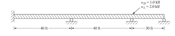
And steel is
Calculation:
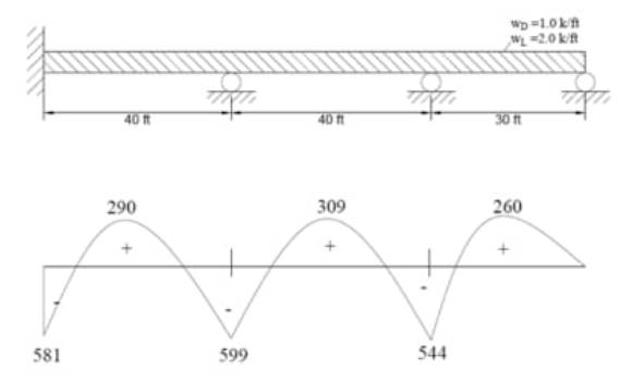
Compute the factored acting on the beam using the equation.
Draw the bending moment diagram with maximum and minimum values.
Using
Calculate the maximum factored positive moment of the beam.
Select a W-section from table 3.2 of the AISC Manual such that.
Since,
Therefore, use
Want to see more full solutions like this?
Chapter 10 Solutions
Structural Steel Design (6th Edition)

- Compute the design moment capacity of a W460x97 with a) Fy = 248 MPa and b) Fy = 345 MPa. Assume the section has full lateral support for its compression flange.arrow_forwardA T-beam section is to be designed to support an ultimate moment of Mu=600kN.m with compression in the flange of the beam. Using bf=650mm, hf=100mm, h=600mm, bw=400mm, f'c=21MPa, fy=415MPa, diameter of the bar=32mm, stirrups diameter=10mm, and concrete cover=40mm, calculate the following: If the entire area of the flange is in compression, calculate the moment strength provided by the flange in kN.m.0 Calculate the depth of compression block necessary to balance the given ultimate moment in kN.m.0 Calculate the area of steel reinforcement necessary to support the ultimate moment in mm2.0 Calculate the depth of compression block of the final section in mm.0 Calculate the ultimate moment capacity of the final section in kN.m.0 need how to solve please thank youarrow_forwardA T-beam section is to be designed to support an ultimate moment of Mu=600kN.m with compression in the flange of the beam. Using bf=650mm, hf=100mm, h=600mm, bw=400mm, f'c=21MPa, fy=415MPa, diameter of the bar=32mm, stirrups diameter=10mm, and concrete cover=40mm, calculate the following: If the entire area of the flange is in compression, calculate the moment strength provided by the flange in kN.m.0 Calculate the depth of compression block necessary to balance the given ultimate moment in kN.m.0 Calculate the area of steel reinforcement necessary to support the ultimate moment in mm2.0 Calculate the depth of compression block of the final section in mm.0 Calculate the ultimate moment capacity of the final section in kN.m.0arrow_forward
- A T-beam section is to be designed to support an ultimate moment of Mu=600kN.m with compression in the flange of the beam. Using bf=650mm, hf=100mm, h=600mm, bw=400mm, f'c=21MPa, fy=415MPa, diameter of the bar=32mm, stirrups diameter=10mm, and concrete cover=40mm, calculate the following: If the entire area of the flange is in compression, calculate the moment strength provided by the flange in kN.m.0 Calculate the depth of compression block necessary to balance the given ultimate moment in kN.m.0 Calculate the area of steel reinforcement necessary to support the ultimate moment in mm2.0 need solution in paper please thank youarrow_forwardA T-beam section is to be designed to support an ultimate moment of Mu=600kN.m with compression in the flange of the beam. Using bf=650mm, hf=100mm, h=600mm, bw=400mm, f'c=21MPa, fy=415MPa, diameter of the bar=32mm, stirrups diameter=10mm, and concrete cover=40mm, calculate the following: If the entire area of the flange is in compression, calculate the moment strength provided by the flange in kN.m.0 Calculate the depth of compression block necessary to balance the given ultimate moment in kN.m.0 Calculate the area of steel reinforcement necessary to support the ultimate moment in mm2.0 Calculate the depth of compression block of the final section in mm.0 Calculate the ultimate moment capacity of the final section in kN.m.0 need answer and solution pleasearrow_forwardSelect the lightest available W8 section (Fy = 50 ksi, Fu = 65 ksi) to support service loads PD = 55 k and PL = 30 k that are placed with an eccentricity of 2.5 in with respect to the y-axis. The member is 12 ft long and is braced laterally only at its supports. Assume Cb = 1.0.arrow_forward
- Use the Effective Length Method, assume elastic behavior, and use both the LRFD and ASD methods. The columns are assumed to have no bending moments Design W12 columns for the bent shown in the accompanying figure, with 50 ksi steel.The columns are braced top and bottom against sidesway out of the plane of the frame so that Ky = 1.0 in that direction. Sidesway is possible in the plane of the frame, the x-x axis. Design the right-hand column as a leaning column, Kx = Ky = 1.0 and the left-hand column as a moment frame column, determined from the alignment chart. PD = 350 k and PL = 240 k for each column.The beam has a moment connection to the left column, and has a simple or pinned connection to the right column.arrow_forwardJ 3 A simple T-beam with bf=600mm, h=500mm, hf=10mm, bw=300mm with a span of 3m, reinforced by 5-20mm diameter rebar for tension, 2-20mm diameter rebar for compression is to carry a uniform dead load of 20kN/m and uniform live load of 10kN/m. Assuming fc'=21Mpa, fy= 415Mpa, d'=60mm, cc=40m and stirrups= 10mm (Calculate the cracking moment)arrow_forward[1.] a.) If the F = { - 200i + 400j } N , determine the force in each member and state if its in compressions or tension (Cartesian) b.) Using the same given, if the members have a square cross-section with a diagonal of 11.31cm and thickness of 1cm, determine the axial stressess and the factors of safety on each of the member, if the maximum allowable tensile strength is 60kPa and the maximum allowable compressive strength is 70kPa Note : Complete solutions, indicated table data, free body diagrams and proper units UP VOTING! THANK YOU!arrow_forward
- A 5-m simply supported beam is loaded over the whole span with uniform loads of WDL=18kN/m and WLL=15kN/m. Use f'c=28MPa, fy=415MPa, bar diameter=20mm, stirrups=10mm, and concrete cover=40mm. Calculate the depth of the neutral axis of the final section in mm.0 Calculate the ultimate moment capacity of the final section in kN.m.0arrow_forwardProb. #1: Determine the allowable concentrated load @ midspan that may be applied to a W530 X 84.8 Section, having a simple span of 8 m. Neglect the weight of the beam & assume that lateral eist only @ the ends. If another lateral support is provided @ midspan, what concentrated load can be supported ? Use 4 = 1.0 and A36 Steel Cfy= 250MPa).arrow_forwardA 4.0 m rectangular cantilever beam is loaded with ultimate uniform load Wu=45kN/m over the whole span and concentrated load Pu= 70kN at the free end. Using As=6-25mm, b=250mm, h=400mm, f'c=21MPa, fy=276MPa, cc=50mm, and stirrups=10mm, determine the following: Determine the effective depth of the beam in mm.0 Determine the critical shear Vu in kN.0 Determine the load to be carried by the stirrups Vs in kN.0 show clear solution thank youarrow_forward

 Structural Analysis (10th Edition)Civil EngineeringISBN:9780134610672Author:Russell C. HibbelerPublisher:PEARSON
 Principles of Foundation Engineering (MindTap Cou...Civil EngineeringISBN:9781337705028Author:Braja M. Das, Nagaratnam SivakuganPublisher:Cengage Learning
 Fundamentals of Structural AnalysisCivil EngineeringISBN:9780073398006Author:Kenneth M. Leet Emeritus, Chia-Ming Uang, Joel LanningPublisher:McGraw-Hill Education
 Traffic and Highway EngineeringCivil EngineeringISBN:9781305156241Author:Garber, Nicholas J.Publisher:Cengage Learning