
Videos
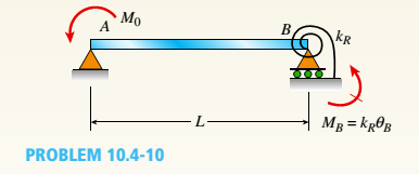
Beam AB has a pin support at A and a roller support at B Joint B is also restrained by a linearly elastic rotational spring with stiffness kR, which provides a resisting moment MBdue to rotation at B. Member AB has flexural rigidity EI. A moment M0acts counterclockwise at B.
- Use the method of superposition to solve for all reactions.
Find an expression for joint rotation

Trending nowThis is a popular solution!

Chapter 10 Solutions
Bundle: Mechanics Of Materials, Loose-leaf Version, 9th + Mindtap Engineering, 1 Term (6 Months) Printed Access Card


- A propped cantilever beam of a length 2L is loaded by a uniformly distributed load with intensity q. The beam is supported at B by a linearly elastic rotational spring with stiffness kR,which provides a resisting moment MBdue to rotation B . Use the method of superposition to solve for all reactions. Also draw shear-force and bending-moment diagrams, labeling all critical ordinates. Let kR= El/L.arrow_forwardSolve the preceding problem for the following data: b = 6 in., b = 10 in, L = 110 ft, tan a = 1/3, and q = 325 lb/ft.arrow_forwardFind support reactions at 4 and Band then use the method of joints to find all member forces. Let b = 3 m and P = 80 kN.arrow_forward
- A cantilever beam is free of support at point A and is clamped at the point B, as showr in the Figure Q4 below. Calculate the support reaction force and moment for the non- uniformly distributed load, where w = 64 N/m and L =6 m. The downward directior is denoted as positive direction in force and the anti-clockwise direction is defined as positve in moment. For all numerical answers, answer to within 3 decimal places. w A B. y Figure Q4: A cantilever beam under non-uniformly distributed load (a) The support reaction force at point B, be careful of the sign. R = (N) (b) The support reaction moment at point B, be careful of the sign. (N*m)arrow_forwardQuestion 2 For the loaded beam shown in the figure below: 25 kN 20 kN 40 kN Im 3 m 5m Figure Q2: Loaded beam 2.1 Determine the reaction forces at the points of support of the beam shown in the figure Q2 above by applying the principle of equilibrium of moments. (Start your solution by drawing a free body diagram of the beam). 22 Develop the equations for shear force andending moment for the spans AB, BC and CD of the loaded beam shown above and for cach equation developed, determine the values of shear force and benángy varnra a' t as A. I1 Pard 5. 2.3 Draw the shear force and bending moment diagrams for the loaded beam shown above.arrow_forwardplease solve with stepsarrow_forward
 Mechanics of Materials (MindTap Course List)Mechanical EngineeringISBN:9781337093347Author:Barry J. Goodno, James M. GerePublisher:Cengage Learning