
Concept explainers
Videos
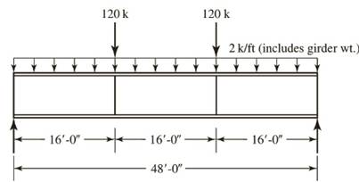
A plate girder must be designed for the conditions shown in Figure P10.7-4. The given loads are factored, and the uniformly distributed load includes a conservative estimate of the girder weight. Lateral support is provided at the ands and at the load points. Use LRFD for that following:
a. Select the, flange and web dimensions so that intermediate stiffeners will he required. Use
b. Determine the locations of the intermediate stiffeners, but do not proportion them.

Trending nowThis is a popular solution!

Chapter 10 Solutions
Steel Design (Activate Learning with these NEW titles from Engineering!)


- The frame shown is subjected to lateral loads of 30 kN and 15 kN acting at joint C and B respectively. The columns are assumed to have equal cross areas. Use Cantilever Method of Analysis.a. Compute the axial load of column EFb. Compute the moment of beam BE at joint B.c. Compute the moment at the base of column AB.arrow_forward34 - A support is a fixed, B support is a sliding joint. loads M= 30 kNm, P1= 12 kN, P2= 13 kN, q1= 6 kN ⁄ m, q2= 7 kN ⁄ m , spans are a= 2 m, b= 3 m. The support reactions in the beam whose loading condition is given in the figure will be found. Accordingly, Ax = ?A) 22.25B) 0C) None.D) 39.25E) 21/2arrow_forwardDetermine ΦMn and Mn/Ω for a W18 x 46 used as a beam with an unbraced length of the compression flange of 4 ft and 12 ft. Use A992 steel and Cb = 1.0.arrow_forward
- For the simple truss shown in the diagram, where the applied vertical downward load PP = 514 N, calculate the load in member AB (in N). Indicate a tensile load as +ve and a compressive load as -ve. Take aa = 2.7 metres.arrow_forwardCompute for the force in members FH, GH, and GI (USE METHOD OF SECTIONS) *For load P, take the last digit of your ID number example: ID # : 2187525, then P= 5 kN IF ZERO IS THE LAST DIGIT, TAKE THE 2ND TO THE LAST DIGIT example: ID #: 2187520, then P= 2 kNarrow_forward4. Design a simply supported beam that will carry an ultimate load of 1750 kN-m. The beam is a W section with a length of 5 m. Use LRFD with F, = 345 MPa, Cb = 1.0.arrow_forward
- The steel frame (E=200 GPa) shown has a diagonal brace BD with an area of 1920 mm2. Determine thelargest allowable load P if the change in length of member BD is not to exceed 2.5 mmarrow_forwardDetermine the radius of the round strut so that the round and square struts have the same cross-sectional area and compute the critical load for each. Use E = 200 GPa.arrow_forward2. A tied column which is subjected to an eccentric load has dimension 300mm x 500 mm which is reinforced with 4D32 as shown. If eccentricity, e = 125 mm, fc’ = 21 MPa, and fy = 414 MPa, compute the following: a. stresses in the steelb. nominal load, Pnc. nominal moment capacity, Mnarrow_forward
- A standard HS truck is moving across a 25-m simple span. The wheel loads are Pa = 36 kN, Pb = 142 kN, and Pc = 142 kN. The distance between Pa and Pb is 4.2 m while Pb and Pc is 7.6 m. a.) Determine Maximum Shearb.) Determine Maximum Moment Provide ILLUSTRATIONS and FBD Use 3 decimals Show complete solutionarrow_forwardA.) If the F = { - 200i + 400j } N , determine the force in each member and state if its in compressions or tension. A.) Using the same given, if the members have a square cross-section with a diagonal of 11.31cm and thickness of 1cm, determine the axial stressess and the factors of safety on each of the member, if the maximum allowable tensile strength is 60kPa and the maximum allowable compressive strength is 70kPa NOTE: Complete solution and units, free body diagrams, table data if possible <up voting!>arrow_forwards shown in the sketch, an interior column AB in a steel frame carries a factored axialcompressive load, Pu = 1540 kips. The column is braced at the top and bottom and the mid-height in the perpendicular plane, and sidesway in the plane of the steel frame is allowed. Thecolumns are 12-ft long, and the columns above and below the column AB are the same size asAB. The adjacent girders are W 18×50 and are 32-ft long. Use A992 steel with Fy = 50 ksi,select the lightest W-section for the column AB. Use stiffness reduction factor where applicable.arrow_forward
 Steel Design (Activate Learning with these NEW ti...Civil EngineeringISBN:9781337094740Author:Segui, William T.Publisher:Cengage Learning