
Concept explainers
Find all the reactions of the beam, draw the shear force and bending moment diagram, and determine the deflection at the midspan of segment BC.
Answer to Problem 11P
The slope at B is
The slope at C is
The end moment of member AB is
The end moment of member BA is
The end moment of member BC is
The end moment of member CB is
The end moment of member CD is
The end moment of member CD is
The deflection under the load is
Explanation of Solution
Apply the sign conventions for calculating reactions using the three equations of equilibrium as shown below.
- For summation of forces along x-direction is equal to zero
- For summation of forces along y-direction is equal to zero
- For summation of moment about a point is equal to zero
Determine the fixed end moment of each member as shown below;
Determine the end moments of each member as shown below;
Express the relationship between slope at C and B as follows:
Determine the end moments of each member as shown below;
Apply Equation of equilibrium at joint B;
Determine the slope at C using the relation;
Hence, the slope at B is
Hence, the slope at C is
Determine the end moments of each member as shown below;
Hence, the end moment of member AB is
Hence, the end moment of member BA is
Hence, the end moment of member BC is
Hence, the end moment of member CB is
Hence, the end moment of member CD is
Hence, the end moment of member CD is
Show the free body diagram of support A, span AB, support B, span BC, support C, span CD, and support D as in Figure (1).
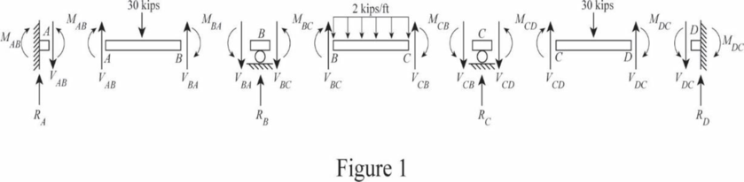
Consider span AB;
Determine the shear
Take moment about A;
Determine the shear
Hence, the vertical reaction at A is
Consider span BC;
Determine the shear
Take moment about B;
Determine the shear
Hence, the vertical reaction at support B is
Consider span CD;
Determine the shear
Take moment about C;
Hence, the vertical reaction at D is
Determine the shear
Hence, the vertical reaction at C is
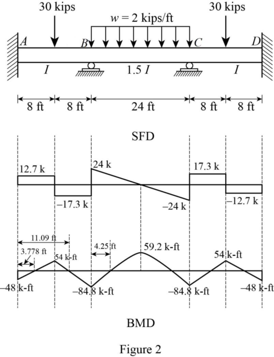
Shear force calculation;
Bending moment calculations;
Consider a section at a distance of x from support A within 8 ft;
Similarly, the bending moment is zero from support D at 3.778 ft.
Consider span AB and DC;
Consider a section at a distance of x (within 16 ft) to determine the where the bending moment is equal to zero;
Similarly, the bending moment is zero from support D at 11.09 ft.
Consider span BC;
Consider a section at a distance of x (within 24 ft) to determine the where the bending moment is equal to zero;
Similarly, the bending moment is zero from support C at 4.25 ft.
Show the shear force and bending moment diagram as in Figure (2).
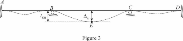
The maximum deflection occurs between span B and C at point E.
Determine the deflection at E under the load using the relations;
Hence, the maximum deflection at E under the load is
Show the deflected shape of the frame as in Figure (3).
Want to see more full solutions like this?
Chapter 10 Solutions
Fundamentals Of Structural Analysis:


 Structural Analysis (10th Edition)Civil EngineeringISBN:9780134610672Author:Russell C. HibbelerPublisher:PEARSON
 Principles of Foundation Engineering (MindTap Cou...Civil EngineeringISBN:9781337705028Author:Braja M. Das, Nagaratnam SivakuganPublisher:Cengage Learning
 Fundamentals of Structural AnalysisCivil EngineeringISBN:9780073398006Author:Kenneth M. Leet Emeritus, Chia-Ming Uang, Joel LanningPublisher:McGraw-Hill Education
 Traffic and Highway EngineeringCivil EngineeringISBN:9781305156241Author:Garber, Nicholas J.Publisher:Cengage Learning